I'll be curious to hear what she tips the scales at. Hope you know a good chiropractor, lol. All teasing aside I can't wait to see it finished. And your how you like it.
Nick
Nick
maybe time to consider chassis on wheels
imagine if dog pulls cables, amp would fall down on floor, leaving some crater behind
imagine if dog pulls cables, amp would fall down on floor, leaving some crater behind
maybe time to consider chassis on wheels
imagine if dog pulls cables, amp would fall down on floor, leaving some crater behind
Dog pulls cables, amp falls on dog, problem solved.
 avesome
 Another update.
I just sent my two machined front panels off to Front Panel Express for engraving, infilling and powder coating; I cut the holes for the Simpson milliammeter and pushbutton HV switch (low voltage momentary to trigger the soft-start relay) using hole saws and a drill press, then decided to get it engraved with a nice logo after that and powder coated to match my preamp front panels.
I also sent the top panels to FPE to cut some of the more intricate/precision-required holes; I'll finish off the others with my drill press when I get them back.
My OPTs and HV chokes should be shipping any day now. Meanwhile I'm drilling out the rest of the panels and those will be sent back to Landfall Systems for anodizing.
Progress, albeit slow...
Hi Magz,
I thougt You where pulling on the cables...(and the Amp where falling on You..., or may be touching the 2400V B+)
Nice to hear from You...
🙂 Matthias
I thougt You where pulling on the cables...(and the Amp where falling on You..., or may be touching the 2400V B+)
Nice to hear from You...
🙂 Matthias
Hello Matthias,
Thanks for the response.
I built a pair on 833 amp about 10 years ago, I dont listen to them anymore since I have few other amp to play with, but I am interested in upgrading them with better output transformer.
A few years ago a friend bought a pair of 1642 SE (about $600/pr), they are OK but not great, since it has peaking at 20Khz, and low frequency distortion when loaded over 150ma.
You sine wave waveform looked surprisingly good, that's why I am interested to see the frequency response across the spectrum for your amp to see if there is any issue with the output transformer.
Did you buy the HP 8903 audio analyzer? I have one myself and it is a great instrument.
Please post your amp frequency response when you have a chance to measure it.
Thank you.
Unison845,
Here's the description of the amp you previously posted in response to my inquiries:
"In Reply to: Schematics? posted by korneluk on August 6, 2002 at 13:29:07:
I never actually draw the SE833A schematic when I builded it. Here is a description:
Input stage: 12AY7/6072 SRPP capacitor coupled to the input of the driver stage.
Driver stage: KT66 as cathode follower using the primary of Electra-Print 3033 interstage transformer. With about 300V on the plate of the KT66 the cathode will be biased about 20V. The cathode of the KT66 is directly coupled to the Grid of the 833A. Other tube like KT77/KT88 can be substituted here but will make the 833A draw more current. It can be compensated by inserting bias resistor to the cathode of 833A.
Output stage: 833SE @ 1300V, 250ma, it will put out 135 watts when clipped . At this voltage the tube dissipate about 325 watts, the plate turn orange color. Force air cooling is a must. You can also use 800v - 1000V on the plate with bias current of 250ma to get 45 watts - 70 watts. The output transformer used is the EP CU5KB. It will take up to 300ma. I am running withe the cathode of the 833A directly to ground. If the 833A draw more current (depending of driver tube used) cathode bias resistor can be added to decrease bias current.
The EP 3033 will not work as an interstage transformer in Shishido circuit since it is a 1:1 and will not drive the grid 833A deep enough to get significant power.
There you have the circuit description of the 833SE. Use every caution if you want to build an amp using this high voltage.
This amp sounded much better than the 845SE (Tamura 2013 output) and 845PP (Tamura 2012 output). In fact this amp sounded better than any 845 amp that I have builded so far ( I still have to build another 845 PSE using CU5KB and 3033 to compare with). It does have the "big stage sound"of the 845, and more "neutral". The mid and high is very sweet".
Re: Schematics? - Unison845 - SET Asylum
Question: was the EP 3033 choke in the cathode of the KT66?
Hi Magz,
I thougt You where pulling on the cables...(and the Amp where falling on You..., or may be touching the 2400V B+)
Nice to hear from You...
🙂 Matthias
I'm still working on it...full-time job and summer activities slow things down but progress is continuing. Too much invested not to finish...
No, it was in the plate.
Unison845,
Here's the description of the amp you previously posted in response to my inquiries:
"In Reply to: Schematics? posted by korneluk on August 6, 2002 at 13:29:07:
I never actually draw the SE833A schematic when I builded it. Here is a description:
Input stage: 12AY7/6072 SRPP capacitor coupled to the input of the driver stage.
Driver stage: KT66 as cathode follower using the primary of Electra-Print 3033 interstage transformer. With about 300V on the plate of the KT66 the cathode will be biased about 20V. The cathode of the KT66 is directly coupled to the Grid of the 833A. Other tube like KT77/KT88 can be substituted here but will make the 833A draw more current. It can be compensated by inserting bias resistor to the cathode of 833A.
Output stage: 833SE @ 1300V, 250ma, it will put out 135 watts when clipped . At this voltage the tube dissipate about 325 watts, the plate turn orange color. Force air cooling is a must. You can also use 800v - 1000V on the plate with bias current of 250ma to get 45 watts - 70 watts. The output transformer used is the EP CU5KB. It will take up to 300ma. I am running withe the cathode of the 833A directly to ground. If the 833A draw more current (depending of driver tube used) cathode bias resistor can be added to decrease bias current.
The EP 3033 will not work as an interstage transformer in Shishido circuit since it is a 1:1 and will not drive the grid 833A deep enough to get significant power.
There you have the circuit description of the 833SE. Use every caution if you want to build an amp using this high voltage.
This amp sounded much better than the 845SE (Tamura 2013 output) and 845PP (Tamura 2012 output). In fact this amp sounded better than any 845 amp that I have builded so far ( I still have to build another 845 PSE using CU5KB and 3033 to compare with). It does have the "big stage sound"of the 845, and more "neutral". The mid and high is very sweet".
Re: Schematics? - Unison845 - SET Asylum
Question: was the EP 3033 choke in the cathode of the KT66?
Wow, this reminds me of the WWII radar station I worked on in '99 which had 833's used as the driver tubes...
Always wondered if you could make a SET using VT90 Micropup output tubes with forced air cooling... Guess the fans kind of make it not worth the effort...
Always wondered if you could make a SET using VT90 Micropup output tubes with forced air cooling... Guess the fans kind of make it not worth the effort...
Wow, this reminds me of the WWII radar station I worked on in '99 which had 833's used as the driver tubes...
Always wondered if you could make a SET using VT90 Micropup output tubes with forced air cooling... Guess the fans kind of make it not worth the effort...
833a's in a radar station. Must have been pretty low frequencies. I know the some of the fist radars were low. But I didn't think they were that low.
Nick
Think you might find that they have a usable range much higher than you think...
Radar was in its very early infancy though, so it may well have been quite low.
Radar was in its very early infancy though, so it may well have been quite low.
Think you might find that they have a usable range much higher than you think...
Radar was in its very early infancy though, so it may well have been quite low.
Wasn't some of the first radars operating close to 100Mhz?
I know a lot of the radar in WW2 was in the UHF range.
I can find no direct literature linking the use of the 833A to radar, but not everything done in WWII has been published or is still available. I looked through several I.R.E. papers on radar from the Signal Corps Labs in the WWII era.
The very first military radar used in WWII was developed in 1938, the SCR-268-T1. It operated at 110 MHz, there is no mention of the type and number of tubes used, but 110 MHz is well beyond the reach of the 833A. The 833A could have been used as the "modulator". This is a sort of square wave switch to apply power to a pulsed oscillator.
By WWII the SCR-268-T2 had been deveolped. It ran at 240 MHz and used a ring of eight "redesigned" Eimac100TL's. The modulator used a ring of 16 "triodes."
Multiple similar radars were developed before and during the war that ran at frequencies from 110 MHz to 900 MHz using transmitting tubes. Magnetron based radars did not have sufficient range for ground based radars at that time. Receiver noise figures were too high.
During a trip to ESRC's 3 million tube warehouse several years ago, I saw several wicked looking fat bottled tubes made by Western Electric. I wrote down the numbers and Googled, finding that these were for radar modulator use. Most dated from the 50's and were made to deliver a multi amp 20 KV pulse to the radar oscilator.
The 833A is a vacuum tube constructed for medium power oscillator or class B or C amplifier applications. It is a medium-mu power triode with 300 watts CCS or 350 watts ICAS anode dissipation. The long grid and anode leads, plus high internal capacitance, limits this tube to 15-30 MHz maximum frequency.
I have been responsible for the operation of a BT.Harris AM transmitter on Greenland ... it contained four of these tubes ... 2 as a modulator and 2 RF tube. It was quite interesting and I have some tubes that are routinely replaced ... they are fine. I do not intend to use them for anything...I am afraid of HT.
I have been responsible for the operation of a BT.Harris AM transmitter on Greenland ... it contained four of these tubes ... 2 as a modulator and 2 RF tube. It was quite interesting and I have some tubes that are routinely replaced ... they are fine. I do not intend to use them for anything...I am afraid of HT.
Last edited:
The 833A is a vacuum tube constructed for medium power oscillator or class B or C amplifier applications. It is a medium-mu power triode with 300 watts CCS or 350 watts ICAS anode dissipation. The long grid and anode leads, plus high internal capacitance, limits this tube to 15-30 MHz maximum frequency.
I have been responsible for the operation of a BT.Harris AM transmitter on Greenland ... it contained four of these tubes ... 2 as a modulator and 2 RF tube. It was quite interesting and I have some tubes that are routinely replaced ... they are fine. I do not intend to use them for anything...I am afraid of HT.
Your afraid of high voltage, but yet you worked on a tube radio transmitter? Im not judging you. I just wasn't sure. You can do what ever you want.
AM transmitter on Greenland ... it contained four of these tubes
Both Harris and RCA made broadcast transmitters in the 500 watt and 1KW power range using the 833A. That was their intended application.
I have some tubes that are routinely replaced ... they are fine.
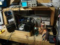
I had 24 tubes that were pulled from broadcast transmitters at routine service intervals. I rigged up a little test amp to test the tubes and a possible OPT for an 833A amp. It put out about 200 watts of audio.
Of the 24 tubes a few were physically damaged (broken glass). One had a visible crack, yet the tube still held vacuum and powered up. I was afraid to run it hard for fear that it would violently shatter. There was another tube with a hole burned into one side of the plate. The glass was darkened from deposited metal. It still made 50 watts or so but distorted a bit. The rest worked good.
Picture of test amp.....note the "tube socket" made with hose clamps and vice grips! Do not try this at home kids....we are trained professionals. 🙂
Attachments
Your afraid of high voltage, but yet you worked on a tube radio transmitter? Im not judging you. I just wasn't sure. You can do what ever you want.
I am not personally afraid... I just don't want it in my home...
What a monster you have made...🙂
- Home
- Amplifiers
- Tubes / Valves
- The Midlife Crisis - My 833C Amp Build