Interesting stuff! And of course your brain waves are great!
Did you also consider any sort of horn design? It's not obvious that you would have with your stand alone towers, but given your crazy brain waves, perhaps not a stretch?
Did you also consider any sort of horn design? It's not obvious that you would have with your stand alone towers, but given your crazy brain waves, perhaps not a stretch?
Actually, I've given a Synergy design a lot of thought. Especially one that has multiple woofers below and above it for the parts below the horn cut-off 🙂.
I couldn't sell that idea to my girlfriend.... she dislikes the big horn speakers. I love them though. Especially the Synergy type.
(or the big old Altec stuff)
I couldn't sell that idea to my girlfriend.... she dislikes the big horn speakers. I love them though. Especially the Synergy type.
(or the big old Altec stuff)
I remember you mentioned those at some point. I was more curious if you considered a "mini" horn for your towers. Perhaps integrated into the cabinet design itself. Or perhaps as "wings" to your cabinet.
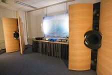
Yes, not too long ago I posted that BD-design array picture, right? Talking of substituting the woofers for an array of smaller TC9 drivers and losing the horn...
Here's a more finished version:

Now there's something I will never be allowed to play with in my house 😀
Here's a more finished version:
Now there's something I will never be allowed to play with in my house 😀
Attachments
Ah, I missed that photo. What you describe is exactly what I was thinking! Are there rules of thumb behind size and shape for the profile?
(hope this is not thread-jacking... I have my separate build thread but this seems like the better place to kick ideas around and the other thread can be actual execution updates.)
(hope this is not thread-jacking... I have my separate build thread but this seems like the better place to kick ideas around and the other thread can be actual execution updates.)

Hahaha, so "my" build thread is good enough to throw out ideas 😀.
Not that that didn't happen before though, and I've been guilty enough to have done just that on other threads. 🙂
It would be interesting enough as a concept. But the things I'd look for is to make any wave guide shape an extension of the actual cone (for the benefit of higher frequencies).
Plus if the sides are actual walls I'd make sure to make that transition as smooth as possible and make the guide part extend down to the lowest frequency possible (means huge wings). The OS profile from Geddes might be a good start, or maybe JMLC could be even better.
https://www.grc.com/acoustics/an-introduction-to-horn-theory.pdf
Will take some time to digest this... but the practical limits of fabrication skills may be the deciding factor here!
Will take some time to digest this... but the practical limits of fabrication skills may be the deciding factor here!
Hahaha, so "my" build thread is good enough to throw out ideas 😀.
Not that that didn't happen before though, and I've been guilty enough to have done just that on other threads. 🙂
I figure this is the ultimate line array thread so these ideas should be aggregated here! Less threads to manage for you and the other experts too.
🙂
https://www.grc.com/acoustics/an-introduction-to-horn-theory.pdf
Will take some time to digest this... but the practical limits of fabrication skills may be the deciding factor here!
The simplest way to make something like that out of wood is to make a frame of the required shape and then fix a thin sheet of bendable ply over the form, a little like a airplane wing construction. Multiple sheets of the ply can be laminated to form a thicker piece or the back cavity filled.
It would be interesting enough as a concept. But the things I'd look for is to make any wave guide shape an extension of the actual cone (for the benefit of higher frequencies).
Plus if the sides are actual walls I'd make sure to make that transition as smooth as possible and make the guide part extend down to the lowest frequency possible (means huge wings). The OS profile from Geddes might be a good start, or maybe JMLC could be even better
Look at RA7's corner line array thread in multiway as he had some measurements and info regarding smoothing out the junction, nc535's synergy corner horn also showed a similar artifact earlier on. The corner mounted idea is great but it is not just as easy as sticking a triangular cabinet in a corner if you want a great result.
Yes, I remember the kerfuffle about the screen edge causing a dip as well as the wall to speaker junction issue. I'm planning a screen myself so it's nice to be able to learn from all the work done here!
I may try the simple 45 degree baffle to start off with (ensuring smooth junctions of course) and then experiment with some foam rollers or something similar to test out the raw response. However, I may be over ruled by my wife on the aesthetics so that may not ever happen!
The simplest way to make something like that out of wood is to make a frame of the required shape and then fix a thin sheet of bendable ply over the form, a little like a airplane wing construction. Multiple sheets of the ply can be laminated to form a thicker piece or the back cavity filled.
I may try the simple 45 degree baffle to start off with (ensuring smooth junctions of course) and then experiment with some foam rollers or something similar to test out the raw response. However, I may be over ruled by my wife on the aesthetics so that may not ever happen!
Much of the studies in Horn theory have been about wave shape. How to get the desired wave shape at the mouth of the horn. Optimisation of phase plugs to get the best wave shape etc.
Research has also been done to see the effects/benefits of smooth transition of CD to the horn.
A corner horn makes it harder to do all of that right. At least without needing to have those drivers (and enclosure volume) sit inside the walls.
We've even seen an experiment with a parabolic/hyperbolic dish shape and a line array firing into that dish by being mounted backwards in front of it.
The line array part:
http://www.diyaudio.com/forums/multi-way/236037-dirty-dozen-line-array.html
The HyperboLine:
https://soundforums.net/forum/pro-audio/varsity/7452-hyperboline-™-new-player-in-the-old-game
Then there's the Beveridge line array. A bit hard to find info on that one. It was an electrostatic speaker with a series of channels in front of it shaped to get the best pattern out of it (which kind of looks like a big phase plug solution):

Patent here: https://www.google.co.uk/patents/US3668335
There's even an example from Tom Danley's using his Paraline solution...

Which isn't firing like a line, more like a point source due to clever use of the paraline lens.
I couldn't really solve corner placement with horn extension in my mind. To me ra7's solution may be as close as you can get but has less enclosure volume available to extend/boost the bottom end than I'd like to have.
After seeing ra7's measurements up close and compare them to my own I noticed less benefit than I expected to see. In fact my own measurements were a bit cleaner. That's when we started to hunt down the source of those troubles, you could say if the walls are your waveguide, basically everything else will be inside your horn.
Vertical planes or edges will show up. As did the screen in his case. Small disruptions in the vertical direction become a common problem that isn't averaged out by the line itself. That's why I keep hammering on the smooth transition being that important. I totally expected the corner horn to blow my results out of the water. It's the fine details that count in a horn like that. All of it solvable but good to keep in mind before you start. Every vertical nook and cranny will show up because it is something in common to all drivers.
To me the biggest advantage is the averaging out of reflections that a line array does. You've seen my results, I do run into trouble at ~70 Hz with the array near a corner on one side. The other side lacks the power on the bottom end but isn't in a full corner so that doesn't show the same 70 Hz problem. So what does that mean? If my room were symmetrical I'd have bigger problems or issues.
I did think about a horn much like the one in your sketch a few posts back, thinking about extending the cone as much as possible and where the waveguide shape hits the walls I would place damping panels. But that isn't too different from the idea of making an enclosure like the Murphy corner array with damping panels on each wall extension I guess.
The array itself will have no trouble to reach down to lower than 200 Hz by itself as you will have power to spare due to the efficiency there. The corner placement can reinforce the bottom end if the walls are flat for a long enough stretch.
I've even thought of the benefit of a lens like the Beveridge in front of the cones and make that feed a horn. That's pretty close to what Danley is doing.
I'm nearing that brain freeze now 🙂.
It seems Fluid agrees with me on the idea of putting damping on both sides 😀
I just found it on your own thread...
If you want to extend the bottom end, make the enclosure big enough, round over the sides and where they meet the wall place (thick enough) damping material. Fiberglass insulation material works very well, combined with wool felt.
If the walls are smooth for a couple of meters (no long vertical nooks and crannies like a door post or screen) you'd get the bottom end reinforcement.
How about painting a screen on the wall? Basically you'd be sitting inside the horn.
Research has also been done to see the effects/benefits of smooth transition of CD to the horn.
A corner horn makes it harder to do all of that right. At least without needing to have those drivers (and enclosure volume) sit inside the walls.
We've even seen an experiment with a parabolic/hyperbolic dish shape and a line array firing into that dish by being mounted backwards in front of it.
The line array part:
http://www.diyaudio.com/forums/multi-way/236037-dirty-dozen-line-array.html
The HyperboLine:
https://soundforums.net/forum/pro-audio/varsity/7452-hyperboline-™-new-player-in-the-old-game
An externally hosted image should be here but it was not working when we last tested it.
Then there's the Beveridge line array. A bit hard to find info on that one. It was an electrostatic speaker with a series of channels in front of it shaped to get the best pattern out of it (which kind of looks like a big phase plug solution):
Patent here: https://www.google.co.uk/patents/US3668335
There's even an example from Tom Danley's using his Paraline solution...
Which isn't firing like a line, more like a point source due to clever use of the paraline lens.
I couldn't really solve corner placement with horn extension in my mind. To me ra7's solution may be as close as you can get but has less enclosure volume available to extend/boost the bottom end than I'd like to have.
After seeing ra7's measurements up close and compare them to my own I noticed less benefit than I expected to see. In fact my own measurements were a bit cleaner. That's when we started to hunt down the source of those troubles, you could say if the walls are your waveguide, basically everything else will be inside your horn.
Vertical planes or edges will show up. As did the screen in his case. Small disruptions in the vertical direction become a common problem that isn't averaged out by the line itself. That's why I keep hammering on the smooth transition being that important. I totally expected the corner horn to blow my results out of the water. It's the fine details that count in a horn like that. All of it solvable but good to keep in mind before you start. Every vertical nook and cranny will show up because it is something in common to all drivers.
To me the biggest advantage is the averaging out of reflections that a line array does. You've seen my results, I do run into trouble at ~70 Hz with the array near a corner on one side. The other side lacks the power on the bottom end but isn't in a full corner so that doesn't show the same 70 Hz problem. So what does that mean? If my room were symmetrical I'd have bigger problems or issues.
I did think about a horn much like the one in your sketch a few posts back, thinking about extending the cone as much as possible and where the waveguide shape hits the walls I would place damping panels. But that isn't too different from the idea of making an enclosure like the Murphy corner array with damping panels on each wall extension I guess.
The array itself will have no trouble to reach down to lower than 200 Hz by itself as you will have power to spare due to the efficiency there. The corner placement can reinforce the bottom end if the walls are flat for a long enough stretch.
I've even thought of the benefit of a lens like the Beveridge in front of the cones and make that feed a horn. That's pretty close to what Danley is doing.
I'm nearing that brain freeze now 🙂.
It seems Fluid agrees with me on the idea of putting damping on both sides 😀
I just found it on your own thread...
If you mount from the rear you will need to have a removable baffle or access to get behind. A removable baffle is harder to seal, so you need lots of fasteners and something to make an airtight seal. Wesayso's aluminium baffle with layers of damping and neoprene does this very well but is pretty complicated.
Mounting from the front is the way I have chosen to go.
An option for you might be to put the cabinet as far into the corner as possible, pack the side gaps with rockwool, felt or other absorbent and then make a fabric grill panel to cover the whole lot.
The walls will provide a waveguide at lower frequencies, the damping will help to reduce or eliminate edge reflections and smooth the wall interface and it's all removable if it doesn't work the way you hoped.
If you want to extend the bottom end, make the enclosure big enough, round over the sides and where they meet the wall place (thick enough) damping material. Fiberglass insulation material works very well, combined with wool felt.
If the walls are smooth for a couple of meters (no long vertical nooks and crannies like a door post or screen) you'd get the bottom end reinforcement.
How about painting a screen on the wall? Basically you'd be sitting inside the horn.
Last edited:
Yes, I just asked RA7 in his thread if he would have done a painted screen in retrospect. And I'll stop contaminating your thread now... thanks for indulging me though.
No problem at all. Just keep in mind that every ridge in parallel with a driver array will potentially cause trouble. I guess you could do a slightly bigger triangular shaped enclosure and "seal" it to the walls (corner of enclosure to wall transition) with damping material. This to absorb at the transition of shapes instead of using a big round over.
wesayso - do you have a photo of your internal wiring? Wondering if you grouped 5 at a time from top to bottom or if you grouped them every fourth driver? And just in general how you made your connections and such.
No photo of that, all of the wiring is beneath a layer of wool felt. Not much to see at all except a pair of wires sticking out to connect to the drivers.
A few pages ago fluid showed a schematic that's 5 in series, 5x parallel. That's how I wired it up. I have two long wires running top to bottom which branch out every 5 drivers.
Shorter wires in between the drivers for the series connections.
I crimped on the appropriate connectors and sealed it off using solder.
I had the advantage to have it on the floor like this:

Here you can see some of the wires sticking out from beneath the wool felt that's used to seal off the fiberglass from the drivers:

The drivers are mounted in pairs with the connectors toward each other, corresponding to the MLV barrier I had in every other brace.
A few pages ago fluid showed a schematic that's 5 in series, 5x parallel. That's how I wired it up. I have two long wires running top to bottom which branch out every 5 drivers.
Shorter wires in between the drivers for the series connections.
I crimped on the appropriate connectors and sealed it off using solder.
I had the advantage to have it on the floor like this:
Here you can see some of the wires sticking out from beneath the wool felt that's used to seal off the fiberglass from the drivers:
The drivers are mounted in pairs with the connectors toward each other, corresponding to the MLV barrier I had in every other brace.
Last edited:
Wow, how much fiberglass and wool did you have in the enclosure? Looks pretty packed! Is the wool there because you were afraid of loose fiberglass getting into the driver motors? Any reason to use fiberglass vs. the polyfil often used? What's MLV? Mass loaded vinyl?
At the binding posts, do you have five wires soldered in together or did you use some sort of terminal strip?
At the binding posts, do you have five wires soldered in together or did you use some sort of terminal strip?
There's still plenty of room between driver and the felt, but yes, there's a quite a fill of fiberglass insulation underneath, the exact amount of it is determined by running impedance tests using my test enclosure.

I've used polyfill only once in an audio project of mine. I wasn't impressed with its performance as I tried to use it at low frequencies at that time. Fiberglass insulation proved to be quite versatile over a very broad range of frequencies. It performed even better when combined with layers of wool felt. The wool felt is used on all walls in the enclosure except the braces There is a double layer of wool felt in the air gaps of the braces though (residing between the fiberglass fill, yes it's that full).
I've tried more than one combination of damping materials and even included Twaron's angel hair in those tests. Fiberglass fill is one of view materials that's effective over the entire spectrum we use in audio. The Angel Hair needed a lesser amount at mid frequencies but couldn't match the fiberglass at lower frequencies.
I didn't want to guess, but instead use measurements to find out what was needed. The impedance plot can tell you a lot about the success of the internal damping materials. You're not the first to comment on the amount I used though.
I didn't have to stuff it in real tight, but it is quite filled top to bottom. You can actually see when you overfill in the impedance measurements. That takes quite a bit of fill though. I used a paper template to cut the fiberglass in the exact amount as used in the text box. Repeatability is important when building arrays. 🙂
Goal was to rid myself of all wiggles in the impedance plot as they would/could amount to direct FR troubles. Compare it with a free air driver measurement for sanity.
Sounds like a lot of work? Actually it isn't. Do this procedure once with a test enclosure containing one driver and repeat that recipe 50 times for the final speakers. Check the final results of course, it showed me I still had some work to do on the baffle.
MLV is indeed mass loaded vinyl. You can see the MLV being used in the brace in the first and last brace on the picture (the black visible part).

I used this to create more room for the connections while still having the first part behind the driver sealed off towards it's neighbour driver.
The binding posts only have 2 wires connected. As said, the rest of them branch out from those 2 wires that run trough the enclosure.
To quote a couple of earlier posts:
I've used polyfill only once in an audio project of mine. I wasn't impressed with its performance as I tried to use it at low frequencies at that time. Fiberglass insulation proved to be quite versatile over a very broad range of frequencies. It performed even better when combined with layers of wool felt. The wool felt is used on all walls in the enclosure except the braces There is a double layer of wool felt in the air gaps of the braces though (residing between the fiberglass fill, yes it's that full).
I've tried more than one combination of damping materials and even included Twaron's angel hair in those tests. Fiberglass fill is one of view materials that's effective over the entire spectrum we use in audio. The Angel Hair needed a lesser amount at mid frequencies but couldn't match the fiberglass at lower frequencies.
I didn't want to guess, but instead use measurements to find out what was needed. The impedance plot can tell you a lot about the success of the internal damping materials. You're not the first to comment on the amount I used though.
I didn't have to stuff it in real tight, but it is quite filled top to bottom. You can actually see when you overfill in the impedance measurements. That takes quite a bit of fill though. I used a paper template to cut the fiberglass in the exact amount as used in the text box. Repeatability is important when building arrays. 🙂
Goal was to rid myself of all wiggles in the impedance plot as they would/could amount to direct FR troubles. Compare it with a free air driver measurement for sanity.
Sounds like a lot of work? Actually it isn't. Do this procedure once with a test enclosure containing one driver and repeat that recipe 50 times for the final speakers. Check the final results of course, it showed me I still had some work to do on the baffle.
MLV is indeed mass loaded vinyl. You can see the MLV being used in the brace in the first and last brace on the picture (the black visible part).
I used this to create more room for the connections while still having the first part behind the driver sealed off towards it's neighbour driver.
The binding posts only have 2 wires connected. As said, the rest of them branch out from those 2 wires that run trough the enclosure.
To quote a couple of earlier posts:
I ran 2 (bigger) wires trough the enclosure and branched from that every 5 drivers. It's following the same schematic you show.
How did you branch it out? Just solder?
Yes, open up the mantle so a piece of bare wire is visible, pry a gap in that wire (multi strand wire) to lock the branch into, twist them firmly together for a lot of physical contact and solder to seal it. A piece of shrink tubing over it to finish it off.
Last edited:
- Home
- Loudspeakers
- Full Range
- The making of: The Two Towers (a 25 driver Full Range line array)