Hard to tell for sure without being able to switch back and forth between the two at the listening spot.
Subjectively I'd say: yes. But that might be the ~ 200 euro I spend on the components persuading me to hear it 😀. It seems more clear, relaxed, well defined. I love the drums on the HR Led Zeppelin stuff. Hard to tell if I'm listening for differences and due to my effort I hear them or that it's really there. Over time I guess it will become more apparent. How's than for an evasive answer 😉.
I've had so many changes and different balance and targets over the past half year... Right now I just put in the right conjugate network and listened. I had to rebalance the channels, about a 0.5 dB difference. Next time I measure I'll look at the FR response differences between network in and out. Also will look for phase differences (if any exist).
Only with a perfect amplifier, there will be no difference between conjugate network or not. Since these don't exist, you are bound to find differences in measurements.
True, but using the FIR filters I probably limit the differences that do exist.
I plan to measure without conjugate network, build a FIR filter for that, measure it and add the conjugate network and measure again, without changing the FIR filter.
That will show the pure differences that are there due to the network.
But measuring with conjugate network in place and basing the FIR correction on that impulse and compare it to the correction made without the network in place is probably going to show less difference in the resulting measurements.
If one listens to a speaker, without EQ and insert a conjugate network and listen again there will probably be more audible differences.
In theory I like what the network does. I went back trough my tests with a single speaker and it shows the same trend on the Group Delay plot as the array does. The conjugate network does straighten that out to a "flat line" quite effectively. Basically as I'm using a Laptop Soundcard for that measurement (with REW) I'm measuring the soundcard's amp.
But it does show the conjugate networks effect, especially since I play these speakers trough their impedance peak. Something that isn't happening that often in other speakers.
Here's a picture showing the Group Delay tab of the array, the corrected array and 3 different test box configurations with a single speaker. Smoothed 1/3 octave to show general trends...

Nice to see the impedance peak of the array is shifted to the left compared to a stuffed single driver in the test box.
Note: this is the Group Delay within an Impedance measurement...
Nice to see the impedance peak of the array is shifted to the left compared to a stuffed single driver in the test box.
Note: this is the Group Delay within an Impedance measurement...
Last edited:
That is a nice improvement on GD with network. Why does your array have a GD bump at impedance peak? Normally GD just rises above 100Hz for sealed alignments?
This is the group delay plot of an impedance measurement. So it's the delay caused by the internal amp of the laptop soundcard while taking that measurement.
Also note the scale on the Group Delay plot, top is 3 ms, bottom -2 ms.
If you look at the plot(s) BYRTT presented earlier in this thread he was plotting the results of an amplifier and the wiring used on the conjugate network.
It's the correcting network that is simulated here, so the result will be the inverse of the (red) graph above:
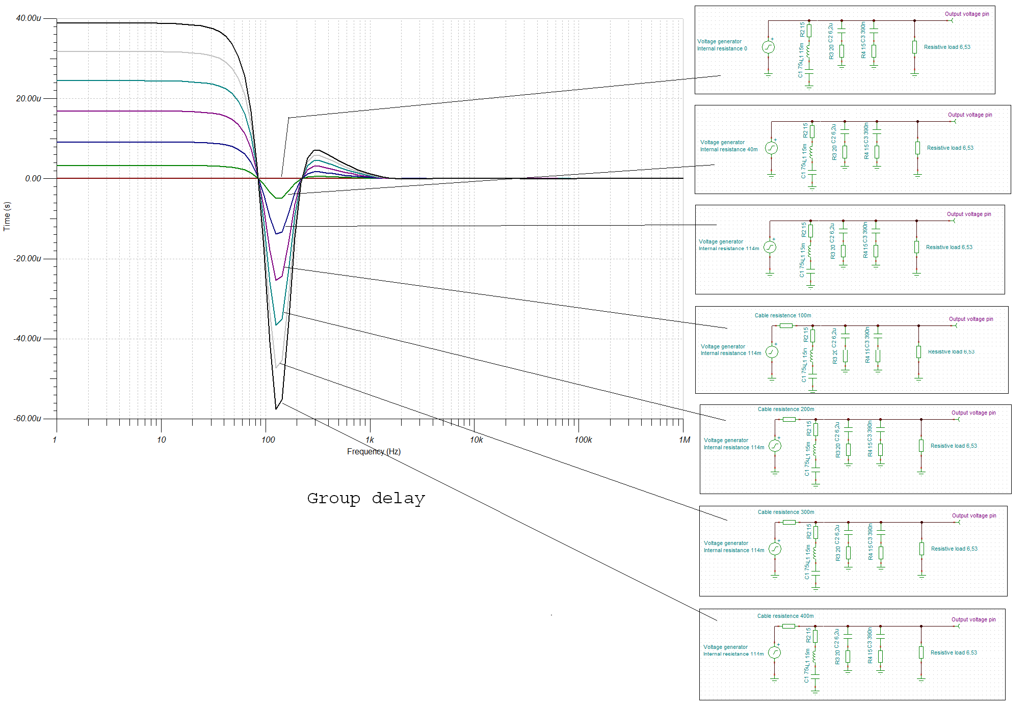
You see the same shapes, though inverted as presented above. I have no plot of my actual amplifier, it could behave entirely different from the laptop I used for these impedance measurements. It will most probably have less GD than the laptop soundcard more in line with the graph from BYRTT. But I don't want to risk frying the laptop soundcard input by leading the output trough the amplifier to the arrays. (Also take note of the scale on the graph BYRTT posted)
The delay is dependant on the resistance of the wiring and the amplifier's damping factor if I am not mistaken. An "ideal" amplifier would have no delay as plotted as a straight line in the graph from BYRTT.
With an accurate conjugate network in place every amplifier would plot like the "ideal" amplifier. The blue line in my plot shows it's pretty close but not perfect.
So I still don't know how big of a difference this all makes with my actual amplifier. It probably is a very small magnitude. Just trying to get some perspective on this whole concept by presenting what I noticed on these impedance graphs and maybe we can actually come up with a reason for perceiving an audible advantage
with a conjugate network in place.
The jury is still out for me even though I did like what I heard today. If I really heard an improvement or not I really can't say yet.
Also note the scale on the Group Delay plot, top is 3 ms, bottom -2 ms.
If you look at the plot(s) BYRTT presented earlier in this thread he was plotting the results of an amplifier and the wiring used on the conjugate network.
It's the correcting network that is simulated here, so the result will be the inverse of the (red) graph above:
You see the same shapes, though inverted as presented above. I have no plot of my actual amplifier, it could behave entirely different from the laptop I used for these impedance measurements. It will most probably have less GD than the laptop soundcard more in line with the graph from BYRTT. But I don't want to risk frying the laptop soundcard input by leading the output trough the amplifier to the arrays. (Also take note of the scale on the graph BYRTT posted)
The delay is dependant on the resistance of the wiring and the amplifier's damping factor if I am not mistaken. An "ideal" amplifier would have no delay as plotted as a straight line in the graph from BYRTT.
With an accurate conjugate network in place every amplifier would plot like the "ideal" amplifier. The blue line in my plot shows it's pretty close but not perfect.
So I still don't know how big of a difference this all makes with my actual amplifier. It probably is a very small magnitude. Just trying to get some perspective on this whole concept by presenting what I noticed on these impedance graphs and maybe we can actually come up with a reason for perceiving an audible advantage
with a conjugate network in place.
The jury is still out for me even though I did like what I heard today. If I really heard an improvement or not I really can't say yet.
Last edited:
Haven't had the chance to do new measurements yet but I can say this: any difference that's there is going to be very small after processing. I managed to put 3 different configurations side by side in REW. Even though the processing settings aren't exactly the same it was obvious the differences were very small.
Not saying it wouldn't make any difference. But I do think the Vifa is behaving quite well with it's shorting rings on its own.
Even with a 10 Ohm series resistor and the conjugation network in line the output was nearly identical after SPL had been corrected. The series resistor might have an advantage in distortion. Still have to run some new tests. But I always fight with the distortion measurements and outside noise here. So it's hard to tell.
One thing I do wonder about is the rising impedance at higher frequencies. It seems counter intuitive to correct for the rising impedance if you want more output up high.
Especially when using series resistance. With the conjugation network in place I had no rise of high frequency level compared to just using the conjugation network.
If I don't correct the rising impedance and use series resistance I might see higher output at those frequencies.
There is a difference in the GD plot between the array without correction and with the conjugate network. The higher in frequency you get, the wider the spread is with the network in place.
The extra damping of the baffle had the opposite effect. Possibly it has to do with the less than optimal amplifying using a laptop for that test though. But it does make me wonder.
A series resistor damps that behaviour while a parallel resistor exaggerates it.
I guess pictures will show more clearly what I'm talking about;
Group delay tap of an impedance measurement of the standard array with Butyl damped baffle:

Same part with conjugate network:

A wider spread at high frequencies is obvious...
Conjugate with a parallel resistor:

Conjugate with a series resistor:

Before adding Butyl instead of mass loaded vinyl it looked more like the spread conjugate network. I did "feel" like the butyl helped clean up the higher frequencies.
So with that in mind, would no correction up top and 10 ohm series resistance give the most benefit? Hard to be sure because the 10 ohm series resistance is also going to limit the power to the array, which will be part of the result, but not all of it. There's no level change in adding the parallel resistor, yet the pattern gets a bit wider with it in use. Same goes for the conjugate network which also puts resistance in parallel with the driver without effecting SPL.
So the series resistance seems to act as a damping mechanism. Made obvious on the laptop measurement. Here's the single driver in the test enclosure with fibreglass insulation filling to compare:

😱
So what would be the ideal situation to choose!
Not saying it wouldn't make any difference. But I do think the Vifa is behaving quite well with it's shorting rings on its own.
Even with a 10 Ohm series resistor and the conjugation network in line the output was nearly identical after SPL had been corrected. The series resistor might have an advantage in distortion. Still have to run some new tests. But I always fight with the distortion measurements and outside noise here. So it's hard to tell.
One thing I do wonder about is the rising impedance at higher frequencies. It seems counter intuitive to correct for the rising impedance if you want more output up high.
Especially when using series resistance. With the conjugation network in place I had no rise of high frequency level compared to just using the conjugation network.
If I don't correct the rising impedance and use series resistance I might see higher output at those frequencies.
There is a difference in the GD plot between the array without correction and with the conjugate network. The higher in frequency you get, the wider the spread is with the network in place.
The extra damping of the baffle had the opposite effect. Possibly it has to do with the less than optimal amplifying using a laptop for that test though. But it does make me wonder.
A series resistor damps that behaviour while a parallel resistor exaggerates it.
I guess pictures will show more clearly what I'm talking about;
Group delay tap of an impedance measurement of the standard array with Butyl damped baffle:
Same part with conjugate network:
A wider spread at high frequencies is obvious...
Conjugate with a parallel resistor:
Conjugate with a series resistor:
Before adding Butyl instead of mass loaded vinyl it looked more like the spread conjugate network. I did "feel" like the butyl helped clean up the higher frequencies.
So with that in mind, would no correction up top and 10 ohm series resistance give the most benefit? Hard to be sure because the 10 ohm series resistance is also going to limit the power to the array, which will be part of the result, but not all of it. There's no level change in adding the parallel resistor, yet the pattern gets a bit wider with it in use. Same goes for the conjugate network which also puts resistance in parallel with the driver without effecting SPL.
So the series resistance seems to act as a damping mechanism. Made obvious on the laptop measurement. Here's the single driver in the test enclosure with fibreglass insulation filling to compare:
😱
So what would be the ideal situation to choose!
Last edited:
Zobel is across driver terminals, and thus directly across amplifier terminals via speaker wire in active system. All this does is dump power.
Convinced yet?
😀 almost...
Seems like sometimes we want something to be superior. But haven't found the evidence it is superior yet. In cases like this it's very hard to only rely on the ears. Though it would form no problem to leave in the network if it only "feels" better. I already have them.
Like I said above, there are differences. But is it an improvement? I've seen cases with series resistance leading to better distortion figures. More than one example on this site.
But 'not every driver is suitable for such an improvement. There also are cases shown where it didn't do anything (useful).
So the jury is still out on that one. Seems like I probably will at least hack the conjugate network to let the impedance rise again at high frequencies. That's not a fault in a line array.
I put a conjugate network across the speakers in a tube type guitar amp I built recently, because of the probability of the amp being jammed into clipping on a regular basis. The idea was that the relatively sharp corners of clipping could cause excessive ringing in the OT at a super sonic frequency, which could cause the speakers to burn out prematurely.
In the case of transistor poweramps that are rarely driven into clipping driving Hi-Fi speakers, it seems like the bigger issue is the amps ability to drive a reactive load without spurious ringing or oscillations.
Putting a 0.5 ohm R in series between the poweramp and the speaker might help this effort significantly as well. Much like when using opamps and putting a 100 ohm R in series with the output driving the load. Then the feedback in the amp has an easier time dominating the phase margin issue. You throw away a few watts in return for a probably better phase margin at all frequencies.
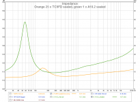
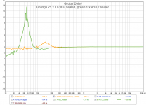
Mine network clearly changed percieved sound, amp PSU did run colder too and clearly visible was motion when cone oscillate was braked considerly. But clearly below plot green color show more resonance my setup compared to line arrays orange and therby more to come for, driver was A10.2 full range speaker without XO. Speaker cables was solid core 0,5mm and their lenght have series resistance around 0,5 ohm.
Attachments
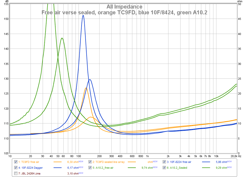
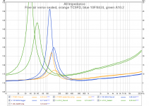
Seems TC9FD have fair flat resonance compared other drivers and then less to correct, here compared 10F/8424 and A10.2.
Orange = TC9FD in free air verse wesayso's right line array.
Blue = 10F/8424 in free air verse xrk971 sealed Dagger.
Green = A10.2 in free air verse sealed relative low Q box.
Orange = TC9FD in free air verse wesayso's right line array.
Blue = 10F/8424 in free air verse xrk971 sealed Dagger.
Green = A10.2 in free air verse sealed relative low Q box.
Attachments
Thanks for posting this, BYRTT, it brings into perspective of what I was chasing 🙂.
I still think I will leave in the "correction" of the resonance bump (as small as it may be) and leave the RC correction (at least the upper one of the two networks I have) out.
It does not rob me of any SPL capability.
Then move on to more tests with series resistance, big and small. That will cost some output potential and will stay only if there's enough benefit to be found. In sound and/or measurements. The sound part can be hard to prove though.
I also would like to know your findings if you're planning to do a correction network on the 10F.
Good to see the GD plot of the A10.2 impulse compared to my array. Now I know it's not just my measurement setup showing results like that in the time domain.
If I want to see this as an exercise to "perfection" of the time domain response, correction up to ~500 HZ would take care of that.
Did you use a laptop/PC for that impulse? Still wondering about different type of amps giving different results in the time domain when presented with reactive loads.
Last edited:
Thanks for posting this, BYRTT, it brings into perspective of what I was chasing 🙂.
I still think I will leave in the "correction" of the resonance bump (as small as it may be) and leave the RC correction (at least the upper one of the two networks I have) out.
It does not rob me of any SPL capability.
Then move on to more tests with series resistance, big and small. That will cost some output potential and will stay only if there's enough benefit to be found. In sound and/or measurements. The sound part can be hard to prove though.
I also would like to know your findings if you're planning to do a correction network on the 10F.
Good to see the GD plot of the A10.2 impulse compared to my array. Now I know it's not just my measurement setup showing results like that in the time domain.
If I want to see this as an exercise to "perfection" of the time domain response, correction up to ~500 HZ would take care of that.
Did you use a laptop/PC for that impulse? Still wondering about different type of amps giving different results in the time domain when presented with reactive loads.
Welcome and thank you too sharing so we have a chance get wiser : )
If you add series resistance to amp wire before the network which should be mounted as close to drivers as possible then into modeling software it shows the network to be more worth it, so therefor in a way hope you find other improvements with series resistance.
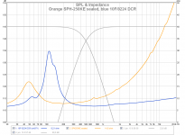
I plan on add it to 10F too and will post findings, but because that speaker is setup as FAST and relative hard XO at 500Hz LR4 (FIR linear phase 🙂 inspired by Barleywater) don't expect it to be very audio able because 10F resonance is mostly cut by XO point, will more expect the RLC/RC network on the woofer will be audio able in that resonance is clearly inside woofers passband (E string on normal 4-string bass guitar sits inside resonance).
Attached is 10F and 250KE Z/GD plots added 500Hz LR4 slopes, don't laugh at 10F strange double resonance curve its because its mounted in a xrk971 DCR box original made and meant for TC9FD, boxes is just for exercises but think good enough to learn from and actual sound pretty good. Picture the setup is here http://www.diyaudio.com/forums/full...3in-5in-drivers-round-2-a-46.html#post4397112.
Attachments

Last edited:
.....Did you use a laptop/PC for that impulse? Still wondering about different type of amps giving different results in the time domain when presented with reactive loads.
Sorry forgot answer that in the above post.
For posted measurements DATS v1 hardware with software package upgraded to v2 is used for A10.2 free air and sealed, free air 10F/8424 and TC9FD. Last two measurements are one is your own 25 x TC9FD array laptop/PC measurement and last one is 10F/8424 in Dagger made by xrk971 with his DATS v2 hardware which include v2 software package. Because this hardware is intended for use to this task and one can calibrate/compare/measure to a reference R/L/C i trust it and compare to reference values always confirm this, including it measures down to 1Hz.
Haven't tried REW to this task because i have that DATS device, think ARTA have a LIMP package to add this function and seen it is praised by many.
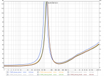
Below is 6 x TC9FD Z-files, first two a batch from Intertechnik and last four a later batch from Europe-Audio, those are measured by DATS device you could import them and compare to your own measured by laptop/PC 🙂. Actual i have 8 x TC9 because later i got two more from US sitting in DCR box created by foam core master himself, they measure in free air exact close to no 2-6, i just only have their in-box files saved and forgot to save their free air files.
Attachments
-
 Z_plot.png70.6 KB · Views: 151
 -
 GD_plot.png65.6 KB · Views: 126
 -
TC9FD_free air_driver1.txt11.7 KB · Views: 102
-
TC9FD_free air_driver2.txt11.7 KB · Views: 113
-
TC9FD_free air_driver3.txt11.7 KB · Views: 115
-
TC9FD_free air_driver4.txt11.7 KB · Views: 108
-
TC9FD_free air_driver5.txt11.7 KB · Views: 132
-
TC9FD_free air_driver6.txt11.7 KB · Views: 113
I really don't get what you are trying to accomplish with these impedance compensation networks. Any good amplifier with sufficiently low Rout will deliver the same voltage to your speaker regardless of whether the filter is in or out. As I posted before, on a good amp, it will be impossible to hear a difference.
On a bad amp, you might, but these days there is no excuse for a bad amp.
On a bad amp, you might, but these days there is no excuse for a bad amp.
Last edited:
Well I have a good reason: I'm broke 😀.
Seriously though... there are a lot of myths in audio... about tricks to better sound. As I am interested in time coherency and that was a big reason to build the arrays I am curious to know if driving a speaker trough it's impedance peak results in a delay at that peak. In my impedance measurements a delay is seen. I bet my amp does not display an equal amount of delay at that peak. That's a bit harder to find.
I'm also interested in current drive. Ideally I would invest in an Ncore amplifier. That would get rid of possible crossover distortion I get with my class AB amp. A class A amp would do me nice also but they don't come at the high power ratings needed for these arrays. That's what triggered these kind of tests.
Usually there is a lot of talk on these kind of subjects but no definitive answers. So I look for my own answers.
If I had unlimited funds and means I would solve way more problems with damping and diffusion. Those funds are not there and I do have restrictions in what I can do to the room if I want to keep my girl. That's why I use arrays and some damping panels and a lot of digital manipulation. But I'm trying to get to a point where I need less manipulation in the digital domain. The least I can get away with anyway. So if that means playing with passive components in an all active setup, why not? I am learning after all.
Who can you really trust to know the truth about all aspects of audio reproduction?
A lot of people disregard time coherency for example. Stating it's simply not audible.
I do not agree with that point of view. Not stating it is audible in the entire 20 to 20 k range either. But I do know what differences I experienced in a lot of experiments on that subject and I have heard an amazing setup in the past.
I have mentioned that system before, it was a small business with the name Mass, here in the Netherlands, at that time developing new ideas under the wings of the Zernike Group. The sole engineer, whom I spoke with on more than one occasion had been in Australia for about 10 years prior to that and also had a business running there. I'll try and get his name but so far I've been unable to find him after ~ 12 years.
He's the one responsible for my quest of a time coherent setup. He tried to explain what he did all those years ago but just now I'm starting to grasp what he was doing. And no, he wasn't using arrays, that my take on this, be it wrong or right 😉.
Just found a bit more info: it was Hans Groothuis of Mass Europe BV.
Way Back Machine to the rescue:
Zernike Group
Anyone on here know (of) him? What he did certainly worked! I remember him flipping his pen around to demonstrate what he did to the soundwaves (lol).
Only me and another colleague were really intrigued with what he did. The colleague had Electrostatic speakers at home but was (more) impressed with the active speakers from Mr. Groothuis. Build in MDF, didn't look like much, connected to a Marantz amp but the sound... wonderful. Even in an untreated conference room.
I am learning after all.
Who can you really trust to know the truth about all aspects of audio reproduction?
Keep up the good work, wesayso - as long as you are enjoying it.
Not that I understand all of what you are doing 🙂 (I am not that advanced by any means), but I really find commendable your:
- Passion and hard work
- Scientific approach, measurements
- Critical listening
- Keeping an open mind, asking questions, willingness to listen to the point of view of others
- Polite and cheerful posts
🙂
Last edited:
Thank you for that, zman01!
At vacuphile and Barleywater, it's not that I don't hear/read what you guys say... I do absorb that information and try to process it with the data found in my own experiments.
I appreciate any knowledge thrown my way.
Why didn't I think of looking up Mass in the internet archives before! It seems Hans Groothuis didn't go after a phase linear system at all. All that had been stuck in my mind from our brief conversations (while he was setting up demo's etc.) was the time manipulation he did to the signal. Years later I just assumed he was talking about creating a time coherent system when in fact he was doing the opposite!
Here's a brief explanation: http://lw3.easy-site.nl/emago_C01/ShowDocument.asp?OriginCode=H&OriginComID=16&OriginModID=533&OriginItemID=0&CustID=651&ComID=16&DocID=6&SessionID=73499276081867171589421073170&Ext=.PDF
I had a hard time following him at the time, knowing way less about this subject at that time. I had searched the internet to find him again without success. But at least I have found some papers now to track down what it was he was doing. And it is way different that what I thought it was, that much is obvious now!
Haven't had time to go trough these but two more patents:
http://amorgignitamorem.nl/FolderForTransfer/Mass_Axdim_Groothuis/WO0143493A1.pdf
http://amorgignitamorem.nl/FolderForTransfer/Mass_Axdim_Groothuis/WO0033623A1.pdf
By the way, the Marantz was only acting as the pre-amp. I've talked to the guys who assisted Mr. Groothuizen to setup a system in a desolated house for testing. They were hugely impressed with his 5.1 system he was testing at that time. I only heard a stereo set that was impressive without the sub active. And also a desktop system run from a laptop. The bigger system could fool you into thinking there was a live band playing while walking past the conference room. To bad I only worked in the same building so I couldn't spend more time bugging him for answers. I almost bought one of his experimental setups for a couple of grand. Ugly looking contraptions with probably scan speak and vifa drivers but it was the internal amplifiers with their 'NLFP' filters that made it special.
- Home
- Loudspeakers
- Full Range
- The making of: The Two Towers (a 25 driver Full Range line array)