If a 2 way with two identical woofers, where one woofer has an additional slightly lower low-pass is called a 2.5 way speaker, then what do I call an array with 5 groups of drivers with 4 groups each having a different low pass.... a 1.?? 🙄
if you really need to give it a designation (or acronym) why not FSA 1.0 (most of my projects all become POS and whatever number)
I wasn't looking for a designation as much, just what would one call a speaker like this.
It isn't a 5 way, or a one way (single driver). One could question if it fits in the full range forum. But I guess even the unshaded array never really fit into this category.
Earlier in this thread I mentioned calling the arrays: Lucid Dreams. So if I'd need a designation it would be LD 2.0. 🙂
The unshaded version would be 1.0, this is quite the big change, so not a 1.something...
All boards are in, here's the graphs separately:

First array

Second array
Overlayed:

Close enough to call it a matched set...
It isn't a 5 way, or a one way (single driver). One could question if it fits in the full range forum. But I guess even the unshaded array never really fit into this category.
Earlier in this thread I mentioned calling the arrays: Lucid Dreams. So if I'd need a designation it would be LD 2.0. 🙂
The unshaded version would be 1.0, this is quite the big change, so not a 1.something...
All boards are in, here's the graphs separately:
First array
Second array
Overlayed:
Close enough to call it a matched set...
Attachments

Last edited:
When I read thread like this I realize I’m much to learn....
Oh my goodness this is amazing build...
Oh my goodness this is amazing build...
Have you any experience with Horbach filters .... like in a 5way
Do you have any links if so? Maybe some good reading ?
Do you have any links if so? Maybe some good reading ?
Thanks for the compliment,
To answer the question you had over on the RePhase thread, my design axis for the arrays is 10 degree off axis.
That gives me the best sound over my entire couch.
Horbach Keele filters? Never played with them as I haven't had the need yet.
I know bbutterfield mentioned them in his (awesome) fractal arrays thread. But he ended up using minimum phase filters.
We must have some users that played with them, nc535 must have by now, as he's been simming arrays and the like for quite a while 😀.
Last edited:
those are the impedance plot,correct? which colors are which driver groups??
do you have the plots for the acoustic response?
do you have the plots for the acoustic response?
These are the filters connected with a series resistor used as a control measurement.
(By shorting the driver groups in the array where the driver is supposed to go)
This test shows me I've wired it all up correctly, as it included moving around driver positions within the array to create a superior listening axis.
I have compared them to the same filter modeled in X-Sim to know I have build them accurately.
As the speakers aren't finished yet, I do not have anything other than Vituixcad sims.
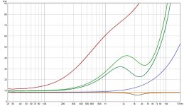
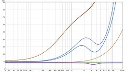
On the top graph (first array) the red plot is the 5 top drivers,
The dark green is the second group from the top,
Dark blue is a split group, 2 above and 3 drivers below the central (listening height) driver group,
Yellow is the central group of drivers, no crossover there,
Light green is the bottom group of 5 drivers.
The two measurements with the dip are alterations of the bottom most driver of the 2 bottom groups, making them act more like the top end (a balancing act to create a wider vertical).
Here you can see the impedance plot of the drivers in the array with filters mounted. That's about as far as I am right now. Second one is ready to be closed and checked like that, but I ran out of time.Will have to wait till next weekend.
Earlier I've posted the schematics and predictions, multiples actually. This above is the schematic 19 as-built, corrected to represent actual filters that I've build.
As I can compare the unshaded sim results with my own measurements I know I can put quite some trust in the predictions. However this still is an experiment. I expect nothing but hope for the best 😉.
(By shorting the driver groups in the array where the driver is supposed to go)
This test shows me I've wired it all up correctly, as it included moving around driver positions within the array to create a superior listening axis.
I have compared them to the same filter modeled in X-Sim to know I have build them accurately.
As the speakers aren't finished yet, I do not have anything other than Vituixcad sims.
On the top graph (first array) the red plot is the 5 top drivers,
The dark green is the second group from the top,
Dark blue is a split group, 2 above and 3 drivers below the central (listening height) driver group,
Yellow is the central group of drivers, no crossover there,
Light green is the bottom group of 5 drivers.
The two measurements with the dip are alterations of the bottom most driver of the 2 bottom groups, making them act more like the top end (a balancing act to create a wider vertical).
Here you can see the impedance plot of the drivers in the array with filters mounted. That's about as far as I am right now. Second one is ready to be closed and checked like that, but I ran out of time.Will have to wait till next weekend.
Earlier I've posted the schematics and predictions, multiples actually. This above is the schematic 19 as-built, corrected to represent actual filters that I've build.
As I can compare the unshaded sim results with my own measurements I know I can put quite some trust in the predictions. However this still is an experiment. I expect nothing but hope for the best 😉.
Last edited:
Today it was snowing, so no finishing up things in the garage. I did get to play a little with the sims, just studying the line behavior. I'll have to wait and see how the new ceiling is going to influence things, but going back to the sims with actual arrays mimicking the floor and ceiling reflections made me re-think the levels. That assumed -4 dB of absorption was based on a certain (quite high) frequency band. In fact I think at some frequencies it may be higher than that, depending on the surface of course.
However, the sim as described above, with copies of the line above and below, teach me a lot more about the line's behavior than using the checkboxes. Highly recommended playing with that, instead of using a simpler model. Yes, it becomes slow and sluggish, but that's what the power PC's are for. I can actually work with it in the latter editions of Vituix. I haven't upgraded to the very last, due to reading nc535's troubles with that one. Although it would probably be save to do so for my specific models.
I do believe all this playing around will help me get a better correction, one that works over a large area, while creating it at the sweetspot. Just a few tweaks here and there should do it. The more I learn, the more I appreciate the array, I can say that much.
Looking forward to future measurements, and experiments. The list of ideas of things to test grows longer and longer 😀.
I've got so much information and ideas floating in my head , I finally figured now would be a good time to write it all down. 12 pages of text supplemented with pictures just to write down my JRiver chain and measurement/DSP plans 😱🙄.
Always knew I was a little crazy. As said, the sims triggered some memories but also new ideas to do the DSP steps all over again. It sure helps to see it this way, controlled in a sim, as it makes even more sense what the measurements made so far showed and why. I'll go about it a bit different, but hopefully better equipped with new knowledge.
Don't ask, I won't share that document. As it is a work in progress and would most probably only make sense to me. Just remember this graph:

If you get what I'm doing here, that's what's written down in separate steps with settings and pictures. With my specific EQ plugins etc. It wouldn't be of any benefit to anyone but me, as I need to redo all of it in my recently renovated room with new filters in my arrays. I see this as preparation to do it all over again. This is a first for me though. I've always relied on the info I remembered, kept it all in my head. Lets see if this will help me get it right more quickly 😀.
Always knew I was a little crazy. As said, the sims triggered some memories but also new ideas to do the DSP steps all over again. It sure helps to see it this way, controlled in a sim, as it makes even more sense what the measurements made so far showed and why. I'll go about it a bit different, but hopefully better equipped with new knowledge.
Don't ask, I won't share that document. As it is a work in progress and would most probably only make sense to me. Just remember this graph:
If you get what I'm doing here, that's what's written down in separate steps with settings and pictures. With my specific EQ plugins etc. It wouldn't be of any benefit to anyone but me, as I need to redo all of it in my recently renovated room with new filters in my arrays. I see this as preparation to do it all over again. This is a first for me though. I've always relied on the info I remembered, kept it all in my head. Lets see if this will help me get it right more quickly 😀.
Attachments

I would certainly like to have a look at that document 😀 but as you say, it wouldn't make any sense to me. Your projects and tweaks are truly inspiring and your wish to share them makes this community richer. I hope to follow some of your steps when I get there with my build, and I hope you can stand a few (or not so few) questions. 🙂
The suspense is killing me! That said, I have learned a great deal from running sims etc, so I do thank you for that! It has given me lots to think about and it will influence my DSP tweaks. I've missed having the speakers around for so long. However, due to the current pandemic I wouldn't have the time (*) alone to listen to them anyway. That made me take it easy and do it right.
The thing I miss the most is going out to see live music! Even though I have been fortunate enough to be close to a scene that made me enjoy live music from time to time, when the situation allowed that to happen (summer last year), it is what I've missed the most.
(*) I have two family members that work/study from home most if not all of the time. Before this pandemic I had time alone at home on every day of the week and one full day a week to play. That day is now spend either with running sims/ideas or in the garage finishing the speakers. I need it to keep me busy, I love this hobby, all sides of it. The building, the thinking, the listening etc.
Last edited:
I've got so much information and ideas floating in my head , I finally figured now would be a good time to write it all down. 12 pages of text supplemented with pictures just to write down my JRiver chain and measurement/DSP plans 😱🙄.
Always knew I was a little crazy. As said, the sims triggered some memories but also new ideas to do the DSP steps all over again. It sure helps to see it this way, controlled in a sim, as it makes even more sense what the measurements made so far showed and why. I'll go about it a bit different, but hopefully better equipped with new knowledge.
Don't ask, I won't share that document. As it is a work in progress and would most probably only make sense to me. Just remember this graph:
If you get what I'm doing here, that's what's written down in separate steps with settings and pictures. With my specific EQ plugins etc. It wouldn't be of any benefit to anyone but me, as I need to redo all of it in my recently renovated room with new filters in my arrays. I see this as preparation to do it all over again. This is a first for me though. I've always relied on the info I remembered, kept it all in my head. Lets see if this will help me get it right more quickly 😀.
isn't the X in circle symbol used for a (RF) mixer? I guess it should be just an additive mixer, so a plus sign in a circle?
like this:

Last edited:
The circled x does mean multiplication. in these diagrams for audio usually it is used for multiplication by a constant. If the multiplicand were time varying (i.e. a sinusoid) the process would generate IM-like distortion products. In RF, the sum or difference product is desired.
If it should be a plus, I'll change it. It is simple sum and/or difference.
In my actual stream it has become a little more complicated as I have split the FIR chain for the mains into mid/side to be able to play with it.
In my actual stream it has become a little more complicated as I have split the FIR chain for the mains into mid/side to be able to play with it.
Last edited:
- Home
- Loudspeakers
- Full Range
- The making of: The Two Towers (a 25 driver Full Range line array)