Yes that network 😱 Glad you did this so I didn't have to 😉
Very good to know that we can trust the floor/ceiling settings in Vituix! Are those the "final" passive networks that you are putting into the arrays now? Surely, many iterations must have been needed to get there. My own are so much simpler but still a huge amount of parameters to tweak. Vituix is marvelous tool, but as you wrote - the endless possibillities can get you stucked in "simulation"-mode forever!
Very good to know that we can trust the floor/ceiling settings in Vituix! Are those the "final" passive networks that you are putting into the arrays now? Surely, many iterations must have been needed to get there. My own are so much simpler but still a huge amount of parameters to tweak. Vituix is marvelous tool, but as you wrote - the endless possibillities can get you stucked in "simulation"-mode forever!
Those are the networks that I'm incorporating into my speakers, yes.
Many many iterations... I numbered them from 1 to 19, but most of those numbers also had an a,b,c,d,e version (lol).
I had to stop somewhere, but not until I came close enough to my goal.
After playing with the separate version, aimed at using a tweeter (just out of curiosity) I even added some tweaks as this did show me what was possible.
A flat response throughout a large area was my goal(*). moving closer or further, up or down. I'm quite pleased with what I got. Even keeping a reasonable 'standing' balance. That part was lower on my scale. As in: less important in my decision making. Most of the listening will be done from the couch, either music listening or Home Theater. So that's where the focus was.
(*) while maintaining a similar overal balance, e.g. not a slowly dropping or climbing result over a large area, as i do know that is something one hears quite easily. Unfiltered arrays have quite a good balance like that, I wanted a result as good or better. I believe I've managed to get just that.
Time will tell if I made the right choices. 😉
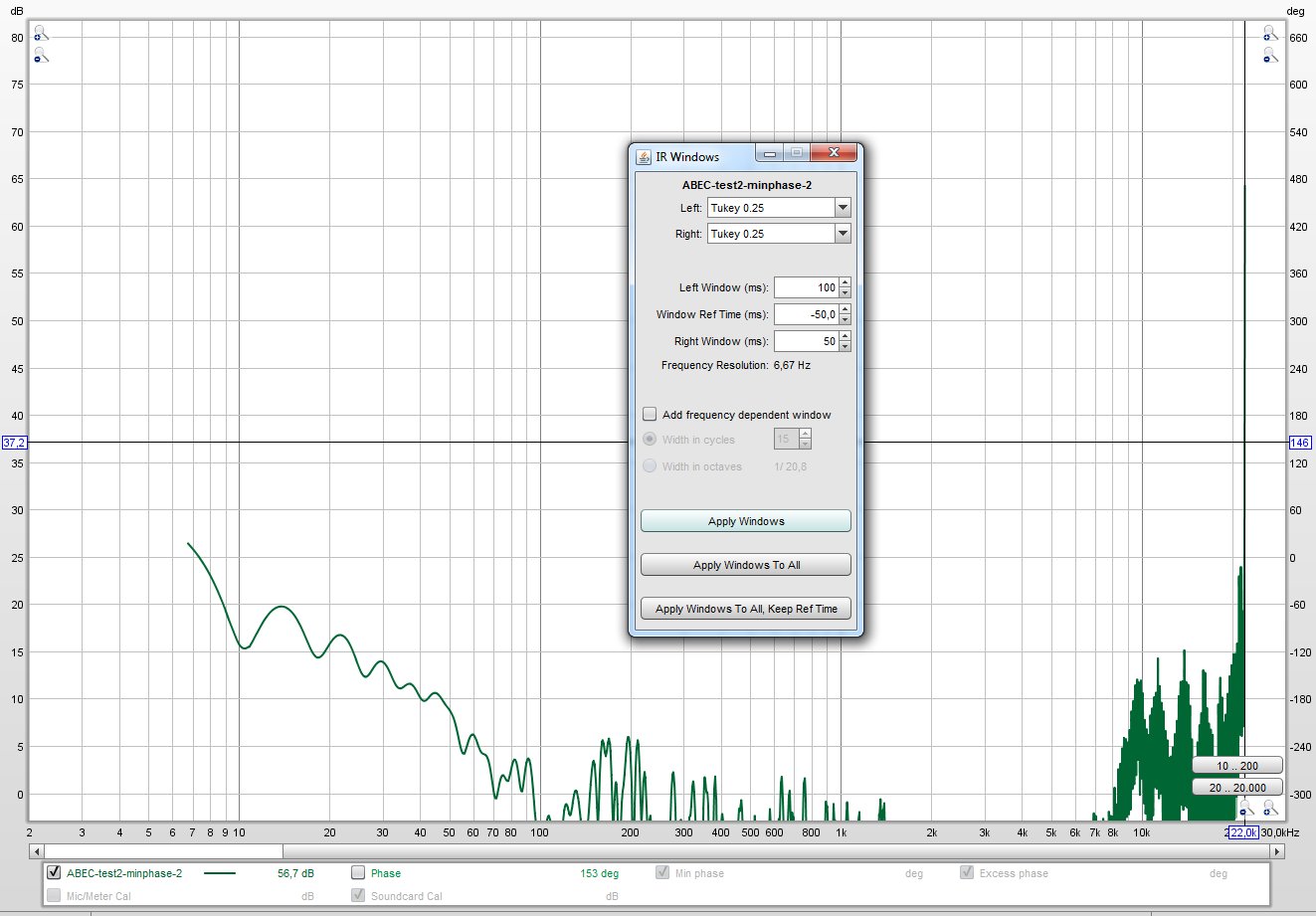
For the longest time I have been interested to find a way to see the other side of my impulse response in REW. You know, a waterfall plot that shows the "on-ramp".
I finally figured out that all I'd need to do is to reverse the audio file and load that into REW. So a quick search gave me this site: Reverse Audio - Audioalter
The reversed Pré IR:

Post IR:

Waterfall plot of the other side of the pré IR:

(notice the 50 dB scale)
And the post convolution IR:

So a simple tool like that would give me all I need... 🙂 A clear view of the other side of the impulse. Now why didn't I think about that any time sooner!
I finally figured out that all I'd need to do is to reverse the audio file and load that into REW. So a quick search gave me this site: Reverse Audio - Audioalter
The reversed Pré IR:
Post IR:
Waterfall plot of the other side of the pré IR:
(notice the 50 dB scale)
And the post convolution IR:
So a simple tool like that would give me all I need... 🙂 A clear view of the other side of the impulse. Now why didn't I think about that any time sooner!
(obviously, most Audio tools will have this feature, sure enough it's there in my ancient Cooledit)
A few days ago I showed this picture on another thread:
It was my way to find the pré ringing output of a measurement/sim etc.
With this reversed IR, we can show it in more detail, with timing...
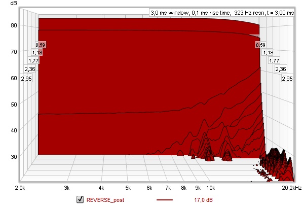
Using a very short rise time (of 0.1 ms) it shows a very similar picture, with even more detail. This picture
above is the result after processing, I'll post the before picture below:

So it's doing quite a clean-up.
It was my way to find the pré ringing output of a measurement/sim etc.
With this reversed IR, we can show it in more detail, with timing...
Using a very short rise time (of 0.1 ms) it shows a very similar picture, with even more detail. This picture
above is the result after processing, I'll post the before picture below:
So it's doing quite a clean-up.
Attachments
I tested the above on a couple of IR's, works like a charm to "see" the other side of the waterfall plot. Now why didn't anyone tell me that earlier 😀.
It was such a "Duhh" moment yesterday, when it finally hit me how simple it really was... Indeed i can do it within Cooledit, and probably many other packages. Anyway, glad it finally came to me as it will be of use to me to see things like pré-ringing or in a case I'll try my hands on cross talk cancellation again.
In fact, I do have some ideas to try, once the arrays are back in action again. I've been trying a few things (virtually) that seem promising.
I've also ordered a new set of wires to make new speaker cables. As mentioned earlier, I went with tinned copper wiring, 12 AWG, ~56x 0,3 mm to 52x 0,31 (tinned) strands (VDE 0295, class 5). I'll dress them up with a flexible tube around the pair.
Temperatures seem to rise at the end of this week, I hope I can make some real progress again. The anticipation is killing me 😀.
Last edited:
~~If the following post makes no sense at all, just skip it.~~
As said I'm working on a new (for me) way to counter cross talk. With arrays, the floor and ceiling influence is strongly diminished on what we get at the listening position. To make matters even more complicated, I have absorbed the early reflections I found in my room. Meaning what's left at the exact sweet spot, is what the direct sound brings me. As I've probably said here and in the Fixing the Stereo Phantom Center thread, I recognized the description in the article. Due to both reasons I mentioned above, I think this effect is stronger with the way I run my arrays than it would be with almost any other speaker. Which is why the mid/side EQ did help quite a bit to correct the effects this cross talk can have on perception.
If I had used a more ideal point source, preferably with CD behavior, while keeping the absorption at first reflections on side wall etc. it would still have floor and ceiling reflections to "help mask" the cross talk dips. We can see that from a Vituixcad plot that shows such a device in a room with only floor and ceiling reflections active. Yes, the left and right energy, arriving a little after the direct sound would be comparable in both ears, but the resulting combing would still mask the hole perceived. Just not quite ideally to really fill it up.
However, it is quite likely that in the mixing or mastering stages, effects like these were solved partially. At least that is the impression I get, when listening to Stereo material compared to multi channel recordings, played back without an actual centre. In the multi channel tracks, the holes are more pronounced, and will vanish somewhat by simply moving a bit to the side. The tonal balance perceived is way different for sounds coming from strong left or strong right compared to the phantom presentation.
Quite the introduction, right?
I can't help but think, if I simulated a floor bounce, as if there was a true center channel there (or a true person, instrument etc.), filling up the hole that I will perceive with my setup, maybe that would sound quite natural, restoring the balance. Being in full control, I could make the "reflection" positive polarity in one channel and negative polarity in the other. All that is left is to decide when such a bounce would need to occur. Basically picking the spot where the (phantom) sound seemed to come from. I'd only want to fill the largest cross talk dip, the one around ~1850 Hz. I can play with strength and timing. The comb pattern that such a simulated reflection would have, would be similar to an actual bounce from sounds coming from that direction/position. Anyway, it could be an interesting experiment.
By now I am convinced that these circumstances are exaggerated by arrays the way I run them (absorbing early reflections and their nature to use floor and ceiling reflections which makes it look like floor and ceiling bounce doesn't happen. (of course it still happens, but it's way harder to recognize it as such, it looks more like the result of a physically larger array).
Anyway, I did run some tests within REW summing a bounce with positive polarity in one channel and negative polarity in the other. Both delayed the same. This does look like a valid way to fill the perceived hole. The early wave front at the ears is very similar for both sides, not creating an imbalance, like the earlier attempts with phase tricks. The timing is a little bit later, the left and right ear both get a slightly different comb, together both ears fill up the gap that otherwise would exist.
I just wanted to write this down for now. It will be a future experiment that I plan to run. I can limit the virtual reflection to the phantom part of the signal, as it shouldn't be present in strong left or right panned signals. Not completely sure yet about the timing, but seeing the sims of the remaining floor/ceiling bounces, especially the ones that I simmed with the mirrored arrays under floor and ceiling actually sparked this preliminary idea.
I had to write it down, as it is running circles in my brain. 😀 May as well write it here, as maybe a response by one of you guys might spark a deeper insight.
Just think of the array in a room vs a single driver as you read the above:
See how there's a big difference in the perceived balance? Don't worry, a single driver does not sound as bad as this graph may indicate, but the floor and ceiling (the only room effects in this picture) do happen to scramble the results right after we've heard the direct sound. If you use even the slightest smoothing, it will look like a nice gated response again. Except at a slightly lower frequency where the flor bounce does throw off the balance somewhat for that single driver solution.
My idea here is to introduce that effect (around the problem frequency *) that would happen "if" there was an actual single source center playing. Applied only to the phantom sum within a stereo signal.
(*) problem frequency depends on the actual setup and the size of one's head. My best estimate for my situation from listening as well as testing with a dummy head suggests somewhere around 1850 Hz.
Using the more known cross talk compensation methods had all kinds of ill side effects within my setup, at least what I've tried so far. I think it makes sense that such setups have the left+right speakers much closer together.
Mid/side EQ helps a lot, but does not cure all of it. I've heard the promise of what 'could be' there. I just wasn't able yet to find a solution that has all advantages and no drawbacks. Well, except for the mid/side EQ.
As it is getting late, I'll post this unedited... hope it makes enough sense to anyone who cares to read it 🙂. I guess it will be far of for most readers that haven't heard the effects that comb filtering has in this obvious or unmasked condition/way. At least that is the impression I got from most responses to Pano's thread.
Attachments
Interesting idea it is definitely an issue for me too. What I don't like so much with the Mid Side EQ is that there is a change in timbre to vocals when compared to without it and listening slightly out of the absolute centre position. So far the MS EQ is a better compromise over all to get an even timbre across an area but it is still a compromise. One of the things I hope to test with a good horn some day 🙂
I think its true that as one optimizes one's setup, effects like you described are unmasked. The crosstalk hole is one example; the difference you and others noticed between amplifiers perhaps being another. I haven't gotten there yet; been moving around too much and constrained re' treatments. The latter is why I'm looking for the design/architecture that needs the least in the way of room treatment.
I found your animated graphic interesting for two reasons. First you showed the difference between the array and a single driver and them implied that a little smoothing erased/minimized the difference. But is that true from an audibility perspective and does it apply to mult-ways as well as single driver? I've explored a number of designs via Vituix simulation and below 2 khz or so, combing and boundary effects don't always disappear with smoothing.
The other thing I noticed was how, except for that rise in the bass, your room response is as flat as your direct response. It took me a while to realize that is one of the best indicators of the quality of shading and system design. In some of the designs I've explored via simulation, when the room response is equalized, the direct response has multiple hills and valleys. In the best, the only effect room equalization is to roll off the direct response due to the boundary support.
But I don't think you want or would have done better with a controlled directivity point source. I think a controlled directivity quasi-infinite line source would be ideal. It would be immune to floor and ceiling and have limited sensivity to the walls. So far I've been frustrated in getting sensible abec sims of such a source.
Interesting idea it is definitely an issue for me too. What I don't like so much with the Mid Side EQ is that there is a change in timbre to vocals when compared to without it and listening slightly out of the absolute centre position. So far the MS EQ is a better compromise over all to get an even timbre across an area but it is still a compromise. One of the things I hope to test with a good horn some day 🙂
I can recommend looking into adding 'controlled ambience' as an expansion of what you have so far. I do feel like I already have quite the controlled tonality overall, and a wide sweet spot as a result. However, my many experiments seem to indicate there's even more to be had 🙂. So I won't stop experimenting to see if that hunch/feeling is accurate. In a way, as I do use this setup for Home Theater, I do already have a variation of this idea at play. (made with 'very' short reverberation on phantom center using the Lexicon plugin with some custom settings)
Works well for HT, not quite pleased with it for music.
That said, I'm very curious on what your outcome will be with a horn setup. It might have challenges of it's own, but it is worth it to try. How is that CNC coming along? 🙂 Don't get too distracted, keep the focus on what you want to achieve. I will continue to follow horn threads like that and Synergy builds as well. If there was more time in a day I'd build some ATH based Synergies just for the learning experience alone...
I think its true that as one optimizes one's setup, effects like you described are unmasked. The crosstalk hole is one example; the difference you and others noticed between amplifiers perhaps being another. I haven't gotten there yet; been moving around too much and constrained re' treatments. The latter is why I'm looking for the design/architecture that needs the least in the way of room treatment.
I found your animated graphic interesting for two reasons. First you showed the difference between the array and a single driver and them implied that a little smoothing erased/minimized the difference. But is that true from an audibility perspective and does it apply to mult-ways as well as single driver? I've explored a number of designs via Vituix simulation and below 2 khz or so, combing and boundary effects don't always disappear with smoothing.
The other thing I noticed was how, except for that rise in the bass, your room response is as flat as your direct response. It took me a while to realize that is one of the best indicators of the quality of shading and system design. In some of the designs I've explored via simulation, when the room response is equalized, the direct response has multiple hills and valleys. In the best, the only effect room equalization is to roll off the direct response due to the boundary support.
But I don't think you want or would have done better with a controlled directivity point source. I think a controlled directivity quasi-infinite line source would be ideal. It would be immune to floor and ceiling and have limited sensivity to the walls. So far I've been frustrated in getting sensible abec sims of such a source.
Good point there, I think you already know the answer: no, smoothing won't work well at all positions, especially below 1-2 KHz. But it doesn't mean it will sound bad to us. We do have some remarkable processor between our ears that "takes the room out". Meaning it does hear the first wave front and the following room response, where for a lot of reasons that first wave front does play a larger role in our perception, making the room part more forgiving. Just think of a person you know, wouldn't you recognize his/her voice in whatever room he/she is in? Despite what the room does for your perception of the sound? This is comparable to a well behaved speaker in a reasonable room.
I got exactly what I wanted with the arrays. A level of independence of the room in more than one way. The filter project will hopefully enhance/better it some more, giving me even better controlled 'in room' behavior.
I don't see it as a draw back. I'll continue to play with it to see how far one can push this idea. At first, after removing the early reflections I was feeling two things: very happy about the increased clarity, sad about the removal of that dynamic energy, mostly gone. Which was insane (in a positive way) with the right orchestral tracks. Adding ambience cured that.
Sure, I do sometimes dream up even better ways to go about it from time to time, but I also like the current challenge, as it has paid off so far. I've already said as much before going down the road of adding the filters; if this is it, I can live with it and be happy. However, as I'm curious by nature, I can't help dream up small incremental improvements. And if I feel they are worthy to try, I will try them 🙂.
Should the above mentioned idea pan out, I will share what I've done and anyone willing to try it can do so. So far I'm still enjoying this and got way more out of it than I expected at the start.
I still believe that it helps to see the room + speakers as a total solution, which in my opinion is where we can get the biggest benefits from in this hobby. I can't place my speakers in another room and expect instant succes. It is the combination that works. Earlier today I tried to say as much on Mabat's thread. Not expecting him to see it this way, but it really is how I see it. He's convinced the best designed speaker will work better in all rooms. I can see how Toole advertises as much, catering to a lot of unknown rooms, but I have to manage what I can and cannot do with my family/girlfriend, in this room that I have with limited options.
The first big hurdle is knowing what it is you want though.... not as easy as it may seem.
Dr. Geddes has a specifically designed room with an absorbent wall behind the speakers, ceiling absorbers, flexible CLD type walls etc... Not something that would get the "OK" here, I'm sure. So one has to get creative with what is possible.
That hasn't gone away as a plan, I have the LSR monitors sitting there waiting but it will be something that sucks up a lot of time so it will be done at some point but not now. My problem is that the tonality without the MS EQ sounds more correct with vocals when not in the shadow position so although the EQ works to deal with the position sensitivity it does something negative to the overall tonality but not so much that it isn't still a better compromise overall.I can recommend looking into adding 'controlled ambience' as an expansion of what you have so far.
I have learnt the most from building/buying different options and trying them out. Learning what you like and don't like is very important.That said, I'm very curious on what your outcome will be with a horn setup. It might have challenges of it's own, but it is worth it to try.
It has stalled because I have found a few issues that I know are going to annoy/cause problems later. I didn't put enough thought into the whole thing initially and with a years gap things have changed. Better ideas are being worked out now 🙂How is that CNC coming along? 🙂 Don't get too distracted
This is a difficult discussion to have and I have stayed out of it there for that reason. A Toole blind test conducted showed that the rating of the speakers tested didn't change between rooms, ergo the conclusion that the better speaker is always the better speaker wherever it is used could easily be assumed, but that isn't what was tested. These were all fairly conventional speakers which is important to note. There has also been a blind test done by Soren Bech where different types of speakers were placed in the room in different positions and the rating of the speakers changed considerably depending on the position. So the room and speaker combination is a factor sometimes. Both are true and do not contradict each other but trying to explain that to anyone who has not done plenty of research themselves is a minefield of confusion.Earlier today I tried to say as much on Mabat's thread. Not expecting him to see it this way, but it really is how I see it. He's convinced the best designed speaker will work better in all rooms.
No one to my knowledge has taken the best rating speakers and blind tested them in different positions and with different levels of acoustic treatment and processing to find out which ends up getting the highest rating overall taking all of those variables into account. That is a test I would like to see.
Last edited:
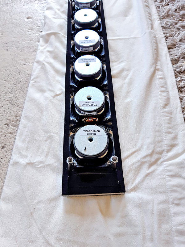
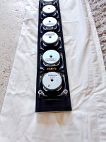
I remember those 🙂.
Martin actually posted about them on this thread: https://www.diyaudio.com/forums/full-range/242171-towers-25-driver-range-line-array-254.html#post4842761
I remember him using a Mohawk anti cross talk devise 😀.
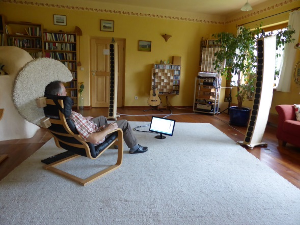
It could become fashionable 😉.
Martin actually posted about them on this thread: https://www.diyaudio.com/forums/full-range/242171-towers-25-driver-range-line-array-254.html#post4842761
I remember him using a Mohawk anti cross talk devise 😀.
It could become fashionable 😉.
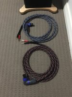
New speaker cables under way. 4 Square mm or 12 AWG, tin plated copper cable. Dressed up with Techflex as promised. I've wondered about the best termination though. Spades, banana plugs etc. Up until now I've always used bare wire ends. I figure that would suit the non corrosive wire ends of this new set as well. Most banana plugs would feature set screws anyway, with isn't dissimilar to just tightening down the current connectors on a bare wire.
The only thing that would make sense is crimped on or soldered spade connectors. But it's one more piece of metal in the mix.
I've also wondered about twisting the wires or just use them as a parallel pair. In the end I went with the last one, parallel pair of wires. Twisting them would lead to less inductance, but upping the capacitance nature.
After reviewing Mr. Pass's excellent paper for the #$W# time it seemed to suit my needs. A coax construction would limit the inductance. However the capacitance would rise. An example of that would be the coaxial speaker wires from Goldmund, using passive correction networks on both ends to counter the raise in capacitance. Not what I'd want to do.
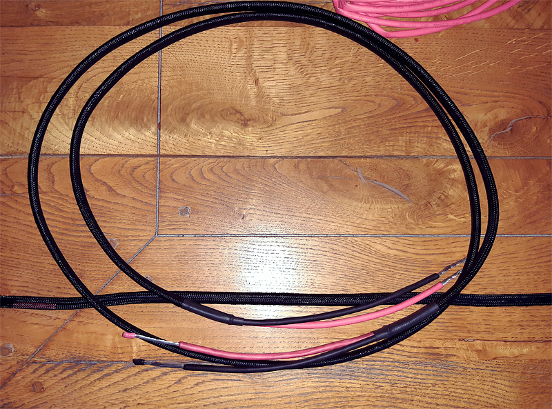
Is this better than lamp cord of a similar size? Well, this one is tin plated to avoid corrosion, and as it is an actual industrial type of wire, it comes with a list of specs it abides to. More than a lot of audio grade wires would give you. 😉
The resistance of this specific wire is 5.09 ohm per 1 km of wire. In the lengths I use that would translate to about 0,1 Ohm.
Without the tin plating the resistance of this same type wire would be 4.7 ohm.
The only thing that would make sense is crimped on or soldered spade connectors. But it's one more piece of metal in the mix.
I've also wondered about twisting the wires or just use them as a parallel pair. In the end I went with the last one, parallel pair of wires. Twisting them would lead to less inductance, but upping the capacitance nature.
After reviewing Mr. Pass's excellent paper for the #$W# time it seemed to suit my needs. A coax construction would limit the inductance. However the capacitance would rise. An example of that would be the coaxial speaker wires from Goldmund, using passive correction networks on both ends to counter the raise in capacitance. Not what I'd want to do.
Is this better than lamp cord of a similar size? Well, this one is tin plated to avoid corrosion, and as it is an actual industrial type of wire, it comes with a list of specs it abides to. More than a lot of audio grade wires would give you. 😉
The resistance of this specific wire is 5.09 ohm per 1 km of wire. In the lengths I use that would translate to about 0,1 Ohm.
Without the tin plating the resistance of this same type wire would be 4.7 ohm.
Attachments
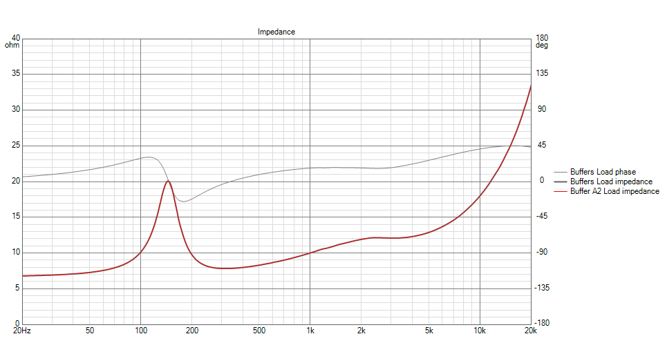
Still studying the Pass document, while adding the suggested 5 Ohm and 0,1 uF to my already present conjugation network in my sim. That does change the presented impedance graph in Vituix.
If I up the capacitor value to 0,01 uF, (as suggested for parallel wires) no change is observed compared to a sim without adding wire resistance etc. Probably not needed with less than 3 meter of wire though. Just trying to come to grips with the concepts that wires could sound different. Not changing to silver here 😀.
But I can see how wire types (more or less inductance in a wire) might influence what we observe. As did a DAC change in my own experience.
I remember in my earlier experiment, where I used the conjugate network to flatten the top end of the impedance, that I didn't particularly liked how that sounded to me.
So even little things like this can have an influence. I was happy with what I got all these years, using a parallel pair of wires of similar thickness as what I've made new.
So all in all I do not expect anything to be (or rather sound) different.
I do remember koldby mentioning he liked to use a coaxial wire as speaker cable. Might be an interesting experiment somewhere, sometime...
The wires I have made up are meant to replace the copper/with clear mantle wires I had on hand when I did my comparison between those and pure single core copper wire (the stuff used for wall outlets).
A smaller gauge multi-stranded wire performed worse in the test back then. I only tested what I had on hand at the time.
My original wires I started with were of the same type as the ones I'm replacing at this moment. Copper wire with semi clear brownish mantle. Those were really old and upon closer inspection turned out to be green of oxidation under the mantle (bought new in ~92 😉). The fact I had to replace them made me do the tests I described with what I had available due to something I had noticed in a measurement of another pair of arrays.
Main lesson: Wires need to be clean and non oxidized. Hence my current choice for tin plated copper.
Last edited:
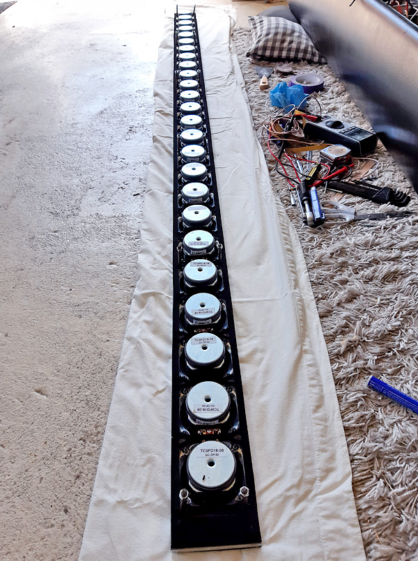
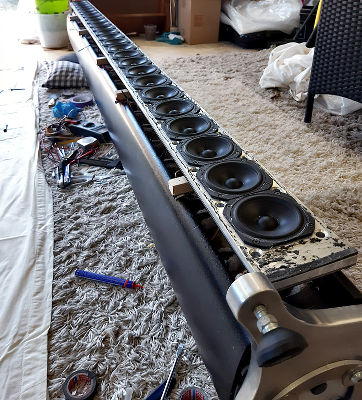
On to the following point of my agenda. Closing up the first array after including the filters. Don't get too exited yet, it's only the inner baffle at this time. I will redo the outside coating before final assembly with outer baffle. 😉
Ran a couple of impedance sweeps, a few before closing up, drivers all hooked up and floating above the enclosure (on a couple of wooden sticks).
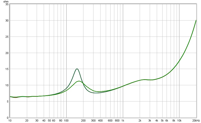
Easy to see the difference with the plots ran after the baffle was mounted in the enclosure.
A comparison to the Vituix simulation:
So far it all seems to check out. Hoping to start on the second array tomorrow!
Have to run now, other life stuff to do... I will probably post some pictures later, even though there's not much to be seen.
Ran a couple of impedance sweeps, a few before closing up, drivers all hooked up and floating above the enclosure (on a couple of wooden sticks).
Easy to see the difference with the plots ran after the baffle was mounted in the enclosure.
A comparison to the Vituix simulation:
So far it all seems to check out. Hoping to start on the second array tomorrow!
Have to run now, other life stuff to do... I will probably post some pictures later, even though there's not much to be seen.
Attachments


New seal on the back of the inner baffle:
A little closer view:
New neoprene seals between enclosure and inner baffle...
Just before sliding it back in, and first testing the impedance this way:
(still some left over residue of the butyl rope)
That's all the pictures I took today. But I'm happy with the results so far.
Impedance checks out, on to the next...
I'm glad I made it all "serviceable". That made this task a lot easier. Still it's a lot of work, especially if the weather doesn't cooperate.
This is a good week though, and I've taken the opportunity to take the week off from work. I've been eyeing the weather forecast since
the start of this year, waiting for a good time to take up vacation days 😀. It coincides with my birthday halfway the week, so all good!
(nothing is more fun than doing what you want to be doing on your birthday 😉)
Attachments


Last edited:
- Home
- Loudspeakers
- Full Range
- The making of: The Two Towers (a 25 driver Full Range line array)