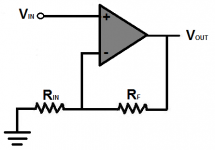
The topology for the Goldmund Telos is actually a very common one and used in 90% of all power amplifiers: Input stage is a differential stage , where the non-inverting input is used as input and the inverting input is used as feedback input. The next stage is the VAS stage (voltage amplification stage) that also is used as a level shifter to match the output stage , witch is merely a current amplification stage. What Hitachi did was, they developed the first complementary pair of Power MOSFets and substituted the bipolar transistors in the current amplifier stage.Trying to understand more about the Goldmund philosophy I was reading a thread on this forum about a Goldmund Memesis.
My impression is that Goldmund took a knows amplifier topology (similar to Hitachi) and optimised it performance by simplifying it while keeping it stable in performance. They continued to do so over a long period up till this day.
A few of the more known names on the amp section of this forum compared it to an F1 car. A highly developed combination of parts to make it do what it does best. However could that make it susceptible to any change in the circuit feeding it?
Which could make sense to me in that it needs certain characteristics of the pré-amp circuit to keep it performing stable? It is after all a very wide frequency spectrum amplifier that differs in many regards from other amplifiers.
Golmund refined this topology with a special and hard to get double J-fet (2N5556) in the DIFF stage and optimized the VAS for very high bandwith without turning the amp into a giant oscillator...
In case of the Telos Goldmund added a driver in front of each Power MOSFet, to isolate the VAS from the nasty capacitive input of these Power MOSFet.
The OP-amp they used (OPA2134) was a decent one at that time (the same Hypex used in their HQ UCD modules) but it certainly has a sonic signature of its own and is surpassed by more recent OP-amps like the ones used in JDS buffer. This was the reason for me to not include this stage in the Goldmund Clone I build (for me, I had no intention, at that time , to sell it).
All the amps I brought along to Wesayso (there was yet a fifth amp we did not audition, as it had XLR input) I had build to find the one that I would use in my system.
Okay i'm too lazy setup simulation for complete amp circuits must take that size 45 then 🙂 but have to say when you conclude or analyze yourself have no problems driving cables from own preamp then why should wesayso's M1 have problems, remember at the meeting HP-1 sat after the long cable run where its just the new ATOM amp that sits before cable run, also that OPA2134 input buffer and DC servo is not configured unity gain but +6dB, probably without knowing the numbers its funny he set ATOM amp to same.I really think your conclusions are wrong. One thing is that it is not the VAS stage that is the input of the Telos clone . The VAS stage is the FTZ transistors whereas the DIFF (diferential) stage is the double fet 2N5556. This is a standard input stage (refined by Goldmund, I will return to this later) and is seen in 90% of all poweramps without any input buffer.
The only reason the original Telos has a input buffer is that it also have a gain setting attenuator, and this calls for a buffer, not the input stage.
And I think I have heard the full potential of the Goldmund chez moi, as I have no problems with driving cables from my preamp. The difference between the three first amps was exactly what I expected. What puzzeled me was that the last candidate underperformed . But I think it was partly because Wesayso are compensating his Line Arrays all the way down and mine are attenuated under 35 Hz or so. This could lead to the last candidate, beeing the least powerfull of the three, would struggle more . I am not at all sure that this was the case as it was also noticeable in more quite passages. I am still puzzled.
Also seen those common differential input stages in lots of Sansui amps and if memory is correct even circuit or most of component values looked the same from model to model few of them had some changes in resistor values probably to ballance out or isolate what source number was expected so as was it variable or frozen and when they later add ballanced input to same circuit they used buffers and was it a 100Ω resistor coupled to differential stage. Think if OPA2134 had a signature reason to omit is very good also that intension was never to sell it, but it actual sold itself 😀The topology for the Goldmund Telos is actually a very common one and used in 90% of all power amplifiers: Input stage is a differential stage , where the non-inverting input is used as input and the inverting input is used as feedback input. The next stage is the VAS stage (voltage amplification stage) that also is used as a level shifter to match the output stage , witch is merely a current amplification stage. What Hitachi did was, they developed the first complementary pair of Power MOSFets and substituted the bipolar transistors in the current amplifier stage.
Golmund refined this topology with a special and hard to get double J-fet (2N5556) in the DIFF stage and optimized the VAS for very high bandwith without turning the amp into a giant oscillator...
In case of the Telos Goldmund added a driver in front of each Power MOSFet, to isolate the VAS from the nasty capacitive input of these Power MOSFet.
The OP-amp they used (OPA2134) was a decent one at that time (the same Hypex used in their HQ UCD modules) but it certainly has a sonic signature of its own and is surpassed by more recent OP-amps like the ones used in JDS buffer. This was the reason for me to not include this stage in the Goldmund Clone I build (for me, I had no intention, at that time , to sell it).
All the amps I brought along to Wesayso (there was yet a fifth amp we did not audition, as it had XLR input) I had build to find the one that I would use in my system.
Last edited:
My preamp has a low output impedance and can easily drive my "short" XLR balanced cables, so here is a big difference.Okay i'm too lazy setup simulation for complete amp circuits must take that size 45 then 🙂 but have to say when you conclude or analyze yourself have no problems driving cables from own preamp then why should wesayso's M1 have problems, remember at the meeting HP-1 sat after the long cable run where its just the new ATOM amp that sits before cable run, also that OPA2134 input buffer and DC servo is not configured unity gain but +6dB, probably without knowing the numbers its funny he set ATOM amp to same.
The other thing is that in Weasayso's system the DAC's apparently have problem driving the cables/amp combo at HIGH levels only.
When the HP-1 was inserted after the long RCA cables it provided gain, so the level out of the DAC was reduced. It would probábly have been marginally better, if the HP-1 was before the long RCA. Remember here that without a preamp , before or after the long RCA cables, if Wesayso reduces the volumen out of the DAC (with lower SPL as a consequence) , the sound was as if there had been a preamp in the system, but at the cost of reduced max. SPL.
From the schematic we have a feedback resistor : 7,5 KOhms and a resistor to ground 270 Ohms.The gain is : (7500/270) = 27,78 times.
In dB this is 20xlog(27,78) = 28,8 dB.
The reason it is a little higher than normal is that the normal input voltage for poweramps to have full power output is 2 Volts and as the Goldmund is a 350 Watt amp it has to have more gain to achieve that than a 100 Watt amp.
The input stage of the original Telos has no gain. R feedback is 2k2 and the R to ground is also 2K2. It is only a buffer that drives the attenuator between this input buffer and the power stage.
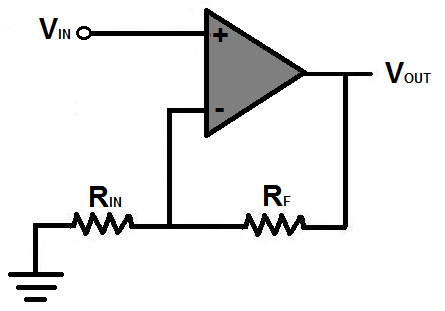
Jus a simple question about the gain, in another (old) thread, using the same opamp in a similar schematic I came across this statement to calculate gain for Noninverting Op Amp Gain:
try changing the feedback lower resistor to 2k
For a 2times gain set the upper feedback resistor to 2k
If you need extra gain change the lower resistor by paralleling another resistor.
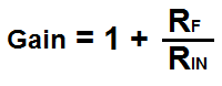
Gain = Upper/Lower +1
2k/2k+1 = 2times
On an amp gain calculator site I found:
Source: Op Amp Gain Calculator
So, much like BYRRT stated, I had figured the gain of the pré amp stage to be 6 dB.
But I do not know enough about this stuff to be stating anything, just trying to learn from it. Would it be valid for me to think this above would apply?
If not, I'd like to learn why not 🙂.
Attachments

Hey guys, the idea of 'can a pre-amp drive a particular length RCA cable?' seems hard to fathom. There have appeared to be comments that this might be so, or rather that cable lengths matter.
I understand and have experienced that longer single ended cables are more susceptible to noise and hum than shorter cables, but have never heard of length presenting a drive level issue (assuming decent cables.)
Am i missing something or interpreting some comments incorrectly...that single ended cable length can create a signal level issue?
I know from outdoor measurements using balanced XLR cables, that a microphones tiny output transmits just fine over hundreds of feet of cable.
And my understanding is that balanced is about noise and hum rejection...and it doesn't boost or change the signal strength in any way.
Is this correct?
If it is, it's hard to see how cable length can matter....for either balanced or unbalanced.....with regard to signal strength transmission.
(and assuming any cable less than a football field in length Lol, and driven from a low impedance output)
Pls straighten me out if i'm seeing things incorrectly, thx 🙂
More food for thought:
1. Sometimes RFI interference can happen with downmixing in ICs. I have an amplifier that I can tune into our local AM talk show to based on the length of cables used. Not sure how many pieces of audio equipment look to limit radio interference at their inputs/outputs.
2. What is not shown on the schematics is the internal wiring harness. Too many times have I seen problems with ground to cases and no attention paid to wall power supply noise rejection ect. A perfect circuit can easily be ruined with dodgy wiring or external connectors being connected in the wrong places.
3. We won't mention expectation bias and double blind testing/level matching as it seems this is known and taken care of in this thread.
I have a hard time thinking a competently designed DAC can not drive a reasonable long RCA cable.
If there is indeed and issue, the DAC would not be the first place I'd look, but I'm incorrect all the time. Measuring the gain as suggested is a great idea as one should rule out subtle clipping problems, both in DAC and AMP. DO you own an oscilloscope? Could scope the output of the DAC to ensure there is no clipping.
You are absolutely right. In a non inverting amp the gain is 1+Rf/Rin so the input stage has +6dB gain. My calculation is for an inverting amp...Jus a simple question about the gain, in another (old) thread, using the same opamp in a similar schematic I came across this statement to calculate gain for Noninverting Op Amp Gain:
On an amp gain calculator site I found:
Source: Op Amp Gain Calculator
So, much like BYRRT stated, I had figured the gain of the pré amp stage to be 6 dB.
But I do not know enough about this stuff to be stating anything, just trying to learn from it. Would it be valid for me to think this above would apply?
If not, I'd like to learn why not 🙂.
So the goldmund has a gain of 1+ 7500/270 = 28,78 in dB: 20 log (28,78) = 29,18dB or 29 dB as Goldmund states.
Hey guys, the idea of 'can a pre-amp drive a particular length RCA cable?' seems hard to fathom. There have appeared to be comments that this might be so, or rather that cable lengths matter.
I understand and have experienced that longer single ended cables are more susceptible to noise and hum than shorter cables, but have never heard of length presenting a drive level issue (assuming decent cables.)
Am i missing something or interpreting some comments incorrectly...that single ended cable length can create a signal level issue?
I know from outdoor measurements using balanced XLR cables, that a microphones tiny output transmits just fine over hundreds of feet of cable.
And my understanding is that balanced is about noise and hum rejection...and it doesn't boost or change the signal strength in any way.
Is this correct?
If it is, it's hard to see how cable length can matter....for either balanced or unbalanced.....with regard to signal strength transmission.
(and assuming any cable less than a football field in length Lol, and driven from a low impedance output)
Pls straighten me out if i'm seeing things incorrectly, thx 🙂
I do not think it is a matter of length per se, but the level that the DAC has to drive the cable at. Mind you that this is not gross clipping or high amounts of distortion rise. It is quite possible that you will have a hard time measuring any difference. But the ears can easily detect an output stage that is not performing optimally.
Last edited:
You are absolutely right. In a non inverting amp the gain is 1+Rf/Rin so the input stage has +6dB gain. My calculation is for an inverting amp...
So the goldmund has a gain of 1+ 7500/270 = 28,78 in dB: 20 log (28,78) = 29,18dB or 29 dB as Goldmund states.
Thanks for confirming that 🙂.
I do not think it is a matter of length per se, but the level that the DAC has to drive the cable at. Mind you that this is not gross clipping or high amounts of distortion rise. It is quite possible that you will have a hard time measuring any difference. But the ears can easily detect an output stage that is not performing optimally.
Indeed, the difference isn't subtle while performance never looked bad when measuring.
More food for thought:
1. Sometimes RFI interference can happen with downmixing in ICs. I have an amplifier that I can tune into our local AM talk show to based on the length of cables used. Not sure how many pieces of audio equipment look to limit radio interference at their inputs/outputs.
2. What is not shown on the schematics is the internal wiring harness. Too many times have I seen problems with ground to cases and no attention paid to wall power supply noise rejection ect. A perfect circuit can easily be ruined with dodgy wiring or external connectors being connected in the wrong places.
3. We won't mention expectation bias and double blind testing/level matching as it seems this is known and taken care of in this thread.
I have a hard time thinking a competently designed DAC can not drive a reasonable long RCA cable.
If there is indeed and issue, the DAC would not be the first place I'd look, but I'm incorrect all the time. Measuring the gain as suggested is a great idea as one should rule out subtle clipping problems, both in DAC and AMP. DO you own an oscilloscope? Could scope the output of the DAC to ensure there is no clipping.
I'm glad I never had a problem like that! The Goldmund clone, even though it is not an amp meant for commercial purposes (koldby was trying to find his own preferred amplifier and tried quite a few different topologies) has been way better at keeping noise out than my old amplifier.
As I've said before, going in the test koldby suggested (trying different amplifiers) I was in a save place, perfectly content with what I had and did not expect to be thrown off. However two of the four amps we tried did exactly that.
I don't have an o-scope, except an ancient model dating back to the early sixties at work and no idea how to operate it. I love it though, one look inside and you realise this thing was built to last. It still works, last recorder service and inspection in the late 80's.
However, I may not chase this down to the bottom but just accept the found cure here. I'd like to chase it down, but where to get the time and knowledge needed? I definitely lack knowledge on the electrical side of things. I know some basics but grew up in a mechanical world. That's where I have my expertise, as well as in IT and that I've simply learned by doing while it became a career for most of my working life.
To learn enough to get me going I just ask stupid questions to the right people. 🙂
This audio game is in itself complicated enough but that's where the fun is for me, so I'll just move on. That is, after figuring out what the best next move will be.
This audio game is in itself complicated enough but that's where the fun is for me, so I'll just move on. That is, after figuring out what the best next move will be.
Too true! Usually optimising a systems gain structure has audible benefits as your ensured to stay within specifications when using the volume control 🙂. I like to have the DACs running as high as signal as possible (without clipping) and gain down the amps to my highest preferred listening level.
Happy Listening!
Did we do distortion measurements on the DAC output?
I did run loopback tests quite a while ago, published some of it in this thread about the IR results and Asio buffers. No strange distortion anomalies were detected compared to the on card DAC of the Xonar device.
I've also shown a loop back of the M1 trough APL-TDA (much like the new wavelet added in REW upon our user request.
I was perfectly happy seeing this:

If something had come up distortion wise I wouldn't have had trouble finding the weak link 😉.
I basically run down all gear I use in tests I can come up with to know where I stand. But as koldby said, some things might not show up that easily, I'd have to agree, reluctantly. It might be possible to find out more, but heck, look in the amplifier forums to know that there's a whole bunch of people devoting their time to find it, while they still cannot agree upon things like this.
I've learned what I needed to, enough to be able to move on. I'll continue to follow threads in the amp forums with one eye, some vendor forums etc. hoping to become wiser.
Just look at Hypex amps. They came highly recommended, yet now we have a new brand by the same designer and where do the people go to?
I could have build myself a Hypex amp for ambience duty. I did use them for my subs, yet I've chosen to go for what I have heard myself and I have trust in the expertise of koldby, who actually knows what he's doing.
One thing I did notice is that the Goldmund clone and the Fetzilla had more in common than they were different. A same sort of signature if we can call it that. Delicious midrange, sweet top end yet detailed. The Goldmund added weight and speed in the bottom end, that really sold it for me.
As my system is for pure entertainment these are good qualities for my taste. Some like more analytical sounding amps. I love it when it triggers my emotions to hear a vocal part. That last part is the terrain of both of these mosfet amps.
I'll never claim amps sound the same ever again. Some things mix better than others.
Last edited:
In comparison speaker drivers and rooms cause much larger errors in our signal stream. Yet the drivers have no choice as to follow what's presented to them.
That's probably where some combinations work better than others.
We're probably talking about real small differences here, yet it may move the cones slightly different and we pick up on that. Either like it or hate it 😀.
I even remember picking up a difference after a software update (JRiver), so I reverted back to a prior state and a few updates later everything was fine again. My measurements did not show any differences though. I may not have been looking hard enough, who knows.
Last edited:
One thing I did notice is that the Goldmund clone and the Fetzilla had more in common than they were different. A same sort of signature if we can call it that. Delicious midrange, sweet top end yet detailed. The Goldmund added weight and speed in the bottom end, that really sold it for me.
This is where I believe if you measure the correct thing, the DUTs will show differences. They must or something other than the DUTs is to blame for the perceived differences.
I do not believe our ears are more sensitive than the current test gear. I concede individuals do not have time to learn and verify everything themselves, I'm the same way regarding mechanical so some things must be taken on faith. When I first got into this hobby I thought it would be easy. 15+ years later, still learning new things!
I've always said, if it sounds different, something must be different. We're just looking in the wrong place. I have a zillion measurements in this thread, not only speakers but also loopback results etc. I do impedance testes on drivers, drivers + box etc. And I think it's fair to say I share more than average, even if it has been a bad experience. But I've got to draw the line somewhere. I do have a life, a family, friends and work to worry about to.
We're basically listening to (and feeling) vibrations here. Our measurements can show vibrations, but do they pick up on small oscillations as well? The measurements are too coarse to find it, and if they could, it wouldn't or couldn't be found in a real room anyway. The measurement gear itself would become one of the parts that would need verification as well. Some things aren't realistic to chase under any other condition than in real lab environments.
I am crazy, but not that crazy 😀.
You may have noticed I do repeat my experiments. I always try to control as many variables as I can. The repeat is for the chance I have missed something or messed it up. I see many people jumping to conclusions while not even making an attempt to control anything. Change one thing at a time, that would be a great start. In our room, we can worry about what it is we hear there. But for things like these we simply lack the time, tools and/or knowledge.
Last edited:
You are certainly right. If we hear differences, there are differences. And test gear is probably more sensitive in measuring exactly that parameter they were designed to measure, but there are zillions of parameters that the ear/brain is working with and only a few of them are appreciated as such and is measurable.This is where I believe if you measure the correct thing, the DUTs will show differences. They must or something other than the DUTs is to blame for the perceived differences.
I do not believe our ears are more sensitive than the current test gear. I concede individuals do not have time to learn and verify everything themselves, I'm the same way regarding mechanical so some things must be taken on faith. When I first got into this hobby I thought it would be easy. 15+ years later, still learning new things!
Just take the example from the 70' Japanese amplifiers. They had vanishingly low distortion parameters and yet they sounded awful.
Then along came a Finish guy who discovered a distortion
phenomenum called Transient IterModulation (TIM) distortion, and that explained the situation.
We are not even close to discover ALL the parameters that the ear/brain uses and that is why, IMHO , things can measure exactly the same , but sound different.
Its been a long time since I did anything with op amps. For small signals, they are near perfect amplifiers - infinite gain, no phase shift, etc . so the feedback around the op amp determines the transfer function. For large signals and high frequencies, you can bump into their limitations - like slew rate limit. A long cable could make that worse if it looks like a capacitive load to the driver. So for understanding what is happening it might help to look at the specs of the op amp chip driving the cable, if available.
Its been a long time since I did anything with op amps. For small signals, they are near perfect amplifiers - infinite gain, no phase shift, etc . so the feedback around the op amp determines the transfer function. For large signals and high frequencies, you can bump into their limitations - like slew rate limit. A long cable could make that worse if it looks like a capacitive load to the driver. So for understanding what is happening it might help to look at the specs of the op amp chip driving the cable, if available.
Hi Jack, quick question...
Is there more to look at in the op amp specs than output impedance?
I've always thought as long as device line output impedance is 250 ohms or below, and cable has decently low capacitance, i could run however long i wanted... ??????
That said, I've seen a fair amount of consumer stuff (miniDSP for example) with a 5-600 ohm output impedance....I figure cause they know too many folks might try to Y outputs together 😀
More than Zout? Surely. slew rate is the first one. We think of an op amp as ideal but there is a limit to how fast its voltage can change. If the ideal op amp transfer function requires the output slew rate to be exceeded than its no longer an ideal device. Its just like operating a driver within its linear limits. As you get deeper into it, there are stability issues: the wrong kind of load for example or phase shift in the feedback loop could turn it into an oscillator. Don't ask too much of the op amp and those things will never come up.
- Home
- Loudspeakers
- Full Range
- The making of: The Two Towers (a 25 driver Full Range line array)