Hi Wesayso:
I applaud your courage and honesty in admitting so publicly to having made a mistake. We all do that from time to time; most of us hate to admit it but its the best way through it.
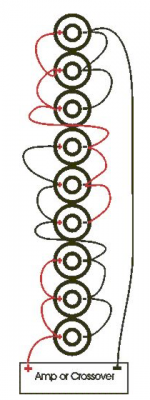
BTW, I think the ground connection at the bottom of the first column of drivers of the parallel series array shouldn't be there.
Jack
I applaud your courage and honesty in admitting so publicly to having made a mistake. We all do that from time to time; most of us hate to admit it but its the best way through it.
BTW, I think the ground connection at the bottom of the first column of drivers of the parallel series array shouldn't be there.
Jack
Yes, correct... I butchered the schematics. But the point was the drivers share the load. So that still applies. Phew.
Hi Wesayso:
I applaud your courage and honesty in admitting so publicly to having made a mistake. We all do that from time to time; most of us hate to admit it but its the best way through it.
BTW, I think the ground connection at the bottom of the first column of drivers of the parallel series array shouldn't be there.
Jack
That´s it! No ground connection there..
Wesayso was not wrong in the first place! The sims are wrong😛
Yes can't beat Ohms law. Each driver will get the same current no matter what wiring scheme (assuming the drivers have good tolerance). Same current = same power dissipation.
I couldn't imagine it any other way but totally missed my messed up schematics.
I had tried some things with frequency dependent shading in mind, long ago.
Note to myself: don't post when you're about to leave in a hurry. 🙂.
I had tried some things with frequency dependent shading in mind, long ago.
Note to myself: don't post when you're about to leave in a hurry. 🙂.
I was wrong about being wrong. 😀Hi Wesayso:
I applaud your courage and honesty in admitting so publicly to having made a mistake. We all do that from time to time; most of us hate to admit it but its the best way through it.
BTW, I think the ground connection at the bottom of the first column of drivers of the parallel series array shouldn't be there.
Jack
So, there I've said it! The Universe still works as it should (fortunately).
But it still was my own mistake not to check things before posting...
I have tried to be upfront with everything, including the mistakes. There should be no need to do it any other way, I hope. Its never easy but it keeps me humble, which is a good thing.
Thanks for this kind message.
Last edited:
I didn't go into hiding, I'm just trying to work out the mid/side EQ. 🙂
I've been listening and currently working out the needed balance to fit with the EQ.
This may take a while, but I'm not disappointed by the first tests.
I've been listening and currently working out the needed balance to fit with the EQ.
This may take a while, but I'm not disappointed by the first tests.
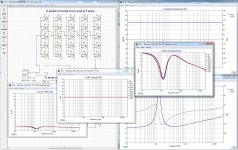
Warning, huge pics!
I've probably posted this before, I can't remember(*). But to raise my faith in our universe, and outline my reason to favor parallel-series wiring once again plots that "should" be right.
(*)= seeing these plots makes me remember I posted exactly that in Fluid's thread. So I really should have remembered and had done the sims before comparing both schemes at a 240 watt load.
First series-parallel (it's what I have):

Versus parallel series (which I still believe to have a slight advantage around the impedance peak, for those that run the arrays full range):

See the differences? This is why I'd still favor parallel series. Both these graphs are with 240 watt(!) to outline the differences.
Series parallel seems to made a difference in voltage swings while parallel series has that effect on current. These drivers (at least the 5 in the bottom of the plots) are based on actual measured impedance curves of the separate drivers to outline these differences. In an enclosure they'd be acting a little different though.
My brain fart earlier on was due to something Mark100 said. If you raise the SLP level by 6 dB, each driver gets to see that 6 dB. While I figured the load would be divided by all drivers. Of course Mark is absolutely right, but a 6 dB raise gets the driver from a next to nothing load to an almost next to nothing load, which is what I was getting at. The drivers do share the load, however throughout most of their frequency range, they hardly do anything at normal listening levels. The bottom EQ to get them to play bass does add up fast though. As I've said before, I raise those levels by about 14 to 16 dB max with EQ, the room fills in the rest. That still doesn't mean that it can sustain a 0 dB peak at 20 Hz, it simply can't. But it does play satisfying bass as found in most music. With a bit of work there's a clear absence of room modes overpowering the bass region. This stays pretty flat throughout the room, spread evenly. It took some work to balance it, and I'll have to redo everything once I add the subs.
Am I right into thinking my impedance peak compensation network does nothing to the driver loads of the above graphs? It merely changes the load at the amplifier? (burning up the added power in the added passive components?)
I've probably posted this before, I can't remember(*). But to raise my faith in our universe, and outline my reason to favor parallel-series wiring once again plots that "should" be right.
(*)= seeing these plots makes me remember I posted exactly that in Fluid's thread. So I really should have remembered and had done the sims before comparing both schemes at a 240 watt load.
First series-parallel (it's what I have):
Versus parallel series (which I still believe to have a slight advantage around the impedance peak, for those that run the arrays full range):
See the differences? This is why I'd still favor parallel series. Both these graphs are with 240 watt(!) to outline the differences.
Series parallel seems to made a difference in voltage swings while parallel series has that effect on current. These drivers (at least the 5 in the bottom of the plots) are based on actual measured impedance curves of the separate drivers to outline these differences. In an enclosure they'd be acting a little different though.
My brain fart earlier on was due to something Mark100 said. If you raise the SLP level by 6 dB, each driver gets to see that 6 dB. While I figured the load would be divided by all drivers. Of course Mark is absolutely right, but a 6 dB raise gets the driver from a next to nothing load to an almost next to nothing load, which is what I was getting at. The drivers do share the load, however throughout most of their frequency range, they hardly do anything at normal listening levels. The bottom EQ to get them to play bass does add up fast though. As I've said before, I raise those levels by about 14 to 16 dB max with EQ, the room fills in the rest. That still doesn't mean that it can sustain a 0 dB peak at 20 Hz, it simply can't. But it does play satisfying bass as found in most music. With a bit of work there's a clear absence of room modes overpowering the bass region. This stays pretty flat throughout the room, spread evenly. It took some work to balance it, and I'll have to redo everything once I add the subs.
Am I right into thinking my impedance peak compensation network does nothing to the driver loads of the above graphs? It merely changes the load at the amplifier? (burning up the added power in the added passive components?)
Attachments

Last edited:
No more time to try and add the impedance compensation, I'm going off line to listen to my latest EQ tweaks with the mid/side EQ revisited.
This is a little flip but it does make my point: I look at both sets of graphs and I see the identical frequency responses so what difference does it make?
Witness also past posted distortion curves and the fact that no drivers have burned out. Surely not worth the effort to rewire when you could instead be inventing more DSP magic.
Were it not for that, I would pose the question as to whether there would be a different answer if random (or actual) variation of driver parameters were simulated. But I 'm really just teasing. I agree with Mark - series parallel vs parallel series should give same results. If they differ if the last decimal place it really doesn't matter. Flatness of impedance isn't much of a concern with active equalization.
I think its sufficient to limit the low end EQ based on measured distortion. If (after bringing in subs) you limit low end distortion in the array on peaks to a few percent that is all you need to do - sound quality is assured and the drivers are protected. Watch out and for that teenage son though.
Not at watts specific. Only in theory. Up till the begon King of this year I had an amp capable of only 100 watt into 8 ohm. That amp gave me a fair warning when things weren't as tbe were supposed to be. All my graphs are callibrated SPL level with a Radioshack SPL meter unless they were virtual excersizes. I've ran sims and compared it to real life to have an understanding of what is going on. Gain structure is one of the most important things to check not to break anything or make it sound nasty.Hi Wesayso, have you looked at watts dissipated with your 14-16 dB low-end boost in place?
Without room/corner placement I wouldn't have been as happy as I am. I haven't bottomed out my drivers in use, aside from maybe a single slip up without correction with the amp probably clipping like crazy. That's where my "ripping your head off" statement came from. I've slipped up more often but with more "safety" levels on the amp side.
Usually I'm still on the save side of things with room to spare. Home Theatre is where there remains a challenge.
I'm simply not as sure as you are. Combined impedance plots can show faint dip/peaks with series/parallel that don't happen as soon with parallel/series. Often only around the impedance peak. These peaks/dips could lead to FR disturbance.This is a little flip but it does make my point: I look at both sets of graphs and I see the identical frequency responses so what difference does it make?
Witness also past posted distortion curves and the fact that no drivers have burned out. Surely not worth the effort to rewire when you could instead be inventing more DSP magic.
Were it not for that, I would pose the question as to whether there would be a different answer if random (or actual) variation of driver parameters were simulated. But I 'm really just teasing. I agree with Mark - series parallel vs parallel series should give same results. If they differ if the last decimal place it really doesn't matter. Flatness of impedance isn't much of a concern with active equalization.
I think its sufficient to limit the low end EQ based on measured distortion. If (after bringing in subs) you limit low end distortion in the array on peaks to a few percent that is all you need to do - sound quality is assured and the drivers are protected. Watch out and for that teenage son though.
I know how this wiring I have reacts but don't yet know much about the other variant. I just may be curious enough to try.
I'm not doing a subwoofer project out of any real need. I was lucky enough to get an offer I could't refuse and again, I am curious enough to try. But I've mentioned that before. They won't feature a 'normal' crossover to the arrays. I know what I want from them, but can't be sure I can actually get it. 🙂
No answers to my question? I know many fail to see an advantage of the impedence peak compensation with my actively driven arrays. I'm not even sure about it to be honest, but that's been documented elsewhere in this thread. It was another curiosity driven experiment.
I've listened to the arrays with and without this compensation and preferred the first. It has remained inline ever since. Both setups were adjusted in the exact same way, meaning separate correction curves following the same target based on new measurements. (I have proven to get very reliable repetative measurements. That's not it. The mic wasn't even moved for this).
I only saw minute changes in the plots, I was looking/hoping for timing changes that didn't happen. It may very well be a mind game with no actual benefit. I paid for the parts so it has to do something, right? 😀
As said: no fail safe prove/test or outcome there. Just a feel, a preference. I did not like the compensation of the rising impedance nor did I like added series resistance.
Last edited:
With a voltage driven amp and where the impedance peak is located, you are in the modal region and will probably need eq anyways. If you are running a solid state amp I'm sure the output impedance is low and nothing to worry about. Instead of just impedance you could also look at electrical phase. The amp will have to work a bit harder around the impedance peak as phase varies to around +/-30 degrees but its pretty tame and not dipping below 6 ohms. I'd say you are more than safe to not bother with passive impedance compensation.
So I was told 🙂. I tried anyway.
Part of the fun for me is learning the hard way. If I had listened to everyone I wouldn't even have started building arrays. I don't regret a minute of it.
Part of the fun for me is learning the hard way. If I had listened to everyone I wouldn't even have started building arrays. I don't regret a minute of it.
Last edited:
Agreed. Building the array was fun! The arrays look the most impressive of the my collection. Always get comments on those.
I broke a lot of router bits trying to machine aluminium with home tools by hand! Does that count? Half the fun is the challenge to make it work!
My pride got a crack (as did the arrays) a couple of times, I think I qualify! 😀
My pride got a crack (as did the arrays) a couple of times, I think I qualify! 😀
- Home
- Loudspeakers
- Full Range
- The making of: The Two Towers (a 25 driver Full Range line array)