Some things simply aren't as clear cut right from the start. I never really believed in audible differences between amps, I only really focused on reliability and good reputation.
That is until we listened to, what was it? 4 different amps with my speakers.
One amp clearly got my heart pumping. While I was able to see differences in measurements explaning some of it, the way the bass transformed was unexpected! So I had to twist koldby's arm to let go of one of his favorites. One of the things gained by using that amp (aside from it's authority in bass) is that it sounds good at all SPL levels. It's like I had to pump up the volume on my old Pioneer to get that, while this Goldmund clone sounds right at each level.
Pioneer A757 Mark II: 100 watt into 8 Ohm
Goldmund Telos 400 clone (or should I say Silverfox): 350 watt into 8 Ohm
The other Mosfet amp, the Fetzilla deserves an honorable mention too! I think that was like 50 watt into 8 ohm, lovely in the midrange. Or do we make up things like that?
I was convinced the Pioneer would be all I ever needed, maybe wanting a bit more power, that's it. I did not expect to favor 2 others before it.
Although this might not be of interest to anyone but me, I just figured to sim "what I have" or close enough to it. I had to adjust to this sim's specific impedance curve, which was based on actual measured drivers in free air.
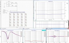
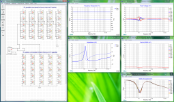
Here's a series-parallel sim with the impedance peak compensation, or at least as close as I could get it in a couple of minutes:

As I would expect, no change in driver voltage/current and/or watts dissipated.
So only the amp load would be different. For a comparison, this is my measured impedance curve with compensation:

Yes, I've put more time in that one, while I got a head start from BYRTT.
Here's a series-parallel sim with the impedance peak compensation, or at least as close as I could get it in a couple of minutes:
As I would expect, no change in driver voltage/current and/or watts dissipated.
So only the amp load would be different. For a comparison, this is my measured impedance curve with compensation:
Yes, I've put more time in that one, while I got a head start from BYRTT.
Attachments
That is indeed a flat Z curve!
could you refresh our memories of what your impedance compensation circuit looks like?
could you refresh our memories of what your impedance compensation circuit looks like?
You can see it on the other graph, but with slightly different values for the main peak than I needed for my specific curve as measured. (The LCR part)
As said, BYRRT did all the hard work, I've adjusted some values after a new impedance measurement.
As said, BYRRT did all the hard work, I've adjusted some values after a new impedance measurement.
The load on the amplifier I'd guess. But no obvious changes between this graph's driver values and the graph I posted this morning. I didn't expect to see any change though.
...So only the amp load would be different...
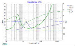
Yes looking in that direction graphs can show that new smooth Z curve amp look into, in below graph from May year 2015 your 25x TC9 is grey curves and after resonance and induction linearization networks is shown as the blue curves for the 25x TC9 array.
Now i would also argue there is another direction that with linearization networks included will short out backwave current that a nervous transducer (spring) develope, so a part of that backwave is hindered (shorted out local) reach back to power amps sensitive feedback network, but probably we could argue about worth of use linearization networks forever but for some it gets a subjective preference. Now it is so that TC9 is one of the most well behaved transducers when it come to relative swing in impedance curve, it have very low resonance and induction variation compared to most transducers out there and for that reason using linearization networks for TC9 is probably less noticeable or worth it. For comparison added the green curves in above graph which is a 10 inch woofer sitting in a sealed Q=1 box and when impedance swing is linearized for that woofer a sound change is very noticeable plus playing a few old recordings that have noticeable LF rumble noice then one can visual see cone is considerly stiffer (none oscillating) with a linearization network than without.
Attachments
As said, with compensation did have my preference. I've only heard it on my arrays though. So it remains hard to say if it had a true advantage.
Compared to the plot shown by BYRRT, I took out the upper most part of the correction, also based on listening. The original schematic had 3 different targets, the impedance pak, the bend at ~2 Khz and the rising upper end. It's in this thread, I'm sure of that.
Like this test, I do remain curious about the parallel/series vs series/parallel. I know what kind of a job it is, I just need to decide if I want to do it and how to find the time to actually do it 😉. Some FR curves from other parallel/series users might convince me some time in the near future. I've seen enough series/parallel to compare it to.
...I do remain curious about the parallel/series vs series/parallel. I know what kind of a job it is, I just need to decide if I want to do it and how to find the time to actually do it 😉...
Had a closer look at original Xsim dxo file you build the closer study with those two flexible schematics to simulate series verse parallel wiring, if i remember correct it was over at Fluid's thread we started it out because opc had some thoughts and real world experience about some woofers that had physical destroyed themselves sitting in series within same cavity and that didn't happen when they were in parallel. Like the unfortunate ground connection back at around post 4921 it really looks we have some human user error that you will hate, so to keep head and mood up lets start quote koldby 🙂
...Wesayso was not wrong in the first place! The sims are wrong😛
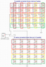
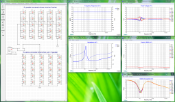
My old XSim dxo file get exactly same variances as in post 4928 so pretty shure below will hold water and then in the end there is no real need to change wiring scheme.
Error is simulation was build upon 5 times different free air impedance curves made by Fluid and those same 5 differences go again from string to string as shown below for the 5 times squared horizontal colors. That means we have variances in series distribution for the lower shematic but for the upper schematic the five series sectors is now a exactly same per sector sum and therefor it show relative perfection about distribution. After changing the upper schematic so that the 5 times different free air measured drivers are sitting as the 5 times squared vertical colors then simulation graphs is exactly the same as shown in the two huge visuals hanged on below, well at a first look then graph "Watts Dissipated" looks a little different but its simply because one can't steer what color belong to what number of drivers for that graph window so look a bit closer and see they actual are exactly the same.
XSim dxo file is also hanged on below in a zip folder.
Attachments
You're not kidding are you? 😱 So the final end conclusion would be: it doesn't matter after all. So Fluid's solution to group drivers to limit this behavior is an adequate solution.
No rewiring plans anymore for me...
Even though I feel kind of stupid about this all, I'm glad we seem to be getting to the bottom of it. One big motivator for me is to break some myths down from time to time, not for everyone, just for my own sense of understanding, does this qualify? It may have qualified if we got to the bottom a little sooner, BYRTT. 😱 However it's never to late to learn. So I'll say it has had its purpose. At least I did not promote anything bad or ill working.
There's so much mystique brought into this hobby and so many stories that I feel it is a good thing to finally get an answer. At least an answer i can believe in. Sadly it doesn't quite change the way I feel 😉.
So this is it for the wiring scheme shootout....
I think I'm going back to my mid/side EQ experiment now. And finish some subs too, to play with. 🙄
Last edited:
So, no difference in parallel-series to series parallel?
I've done my arrays from the beginning using parallel-series, using the premise that it is the closest approximation to full parallel, which is most closest to individually amplified drivers.
In the end tho, gotta respect the science...
I've done my arrays from the beginning using parallel-series, using the premise that it is the closest approximation to full parallel, which is most closest to individually amplified drivers.
In the end tho, gotta respect the science...
You're not kidding are you? 😱 So the final end conclusion would be: it doesn't matter after all. So Fluid's solution to group drivers to limit this behavior is an adequate solution.
No rewiring plans anymore for me...
Even though I feel kind of stupid about this all, I'm glad we seem to be getting to the bottom of it. One big motivator for me is to break some myths down from time to time, not for everyone, just for my own sense of understanding, does this qualify? It may have qualified if we got to the bottom a little sooner, BYRTT. 😱 However it's never to late to learn. So I'll say it has had its purpose. At least I did not promote anything bad or ill working.
There's so much mystique brought into this hobby and so many stories that I feel it is a good thing to finally get an answer. At least an answer i can believe in. Sadly it doesn't quite change the way I feel 😉.
So this is it for the wiring scheme shootout....
I think I'm going back to my mid/side EQ experiment now. And finish some subs too, to play with. 🙄
I also feel kind of stupid in it was my XSim file you took over long ago for deeper moddeling that had that technical layout mistake and myself had never used that file ever since, but good enough then we finally got to the bottom and case closed stamped myth is not any real difference or improvement 😛
Another angle on same subject is go nuts and buy loads of transducers so as to match them or in some mystery test setup make sure whereever there is a series string it is matched to other serie strings but then again how precise can one build multiple enclosure cavitys and distribute multiple dampening plus match multiple tightening of each and every bolt is the question.
Have best experiment with mid/side EQ and finish those nice subs 🙂
You're not kidding are you? 😱 So the final end conclusion would be: it doesn't matter after all. So Fluid's solution to group drivers to limit this behavior is an adequate solution.
No rewiring plans anymore for me...
Even though I feel kind of stupid about this all, I'm glad we seem to be getting to the bottom of it.
The funny thing is I managed to balls up my own idea and put all the series connected drivers in the same sub enclosure instead of different ones 🙄
The good thing is that even in that worst case scenario it all still measured without any issues at all 😉 In one tower I sorted the drivers to have the most similar free air impedance peaks frequency in the same enclosures and that did go some way to making the overall peak less lumpy. It was time consuming but cost nothing else.
With large woofers or drivers with poor unit to unit consistency it might not have worked out so well though...
By the time you have got the mid side EQ tweaked I might have some arrays back in service to try it 🙂
All the drivers in series have the same current flowing through their voice coils. Power = I*I*Z. All the drivers in parallel have the same voltage across them. Power = E*E/Z
So the only difference is due to individual driver Z variation.
I suppose a series string of driver voice coils acts as a delay line to some extent. I haven't done the math to see if the effect is large enough to matter for us. My gut feel is for a low inductance voice coil suitable for full range, the delay won't be significant. I think way back in this thread there was a discussion of trouble with series connected subwoofers.
I hope I'm right because I have 4 strings of 8 series connected drivers.
All the drivers in series have the same current flowing through their voice coils. Power = I*I*Z. All the drivers in parallel have the same voltage across them. Power = E*E/Z
So the only difference is due to individual driver Z variation.
I suppose a series string of driver voice coils acts as a delay line to some extent. I haven't done the math to see if the effect is large enough to matter for us. My gut feel is for a low inductance voice coil suitable for full range, the delay won't be significant. I think way back in this thread there was a discussion of trouble with series connected subwoofers.
I hope I'm right because I have 4 strings of 8 series connected drivers.
I read ages ago in Danish High Fidelity magazine that there are some negative sideeffects to coupling woofer drivers in series, I think it's only related to woofers... or most problematic with woofers (read: large voice coils). I am not sure if it is possible to locate that article now but obviously some people suggest there is a side effect.
If what I think is correct this issues should be much less prominent with small fullrange drivers. Would be good to find out!
Last edited:
So, no difference in parallel-series to series parallel?
I've done my arrays from the beginning using parallel-series, using the premise that it is the closest approximation to full parallel, which is most closest to individually amplified drivers.
In the end tho, gotta respect the science...
This is my thinking also 😛
//
Oh yes. There is certainly a very serious effect, when we are talking about heavy woofers. The damping factor of the poweramp driving the woofer is very important for the bass response, and if you series connect two woofers, the damping factor is reduced to less than 1 !I read ages ago in Danish High Fidelity magazine that there are some negative sideeffects to coupling woofer drivers in series, I think it's only related to woofers... or most problematic with woofers (read: large voice coils). I am not sure if it is possible to locate that article now but obviously some people suggest there is a side effect.
If what I think is correct this issues should be much less prominent with small fullrange drivers. Would be good to find out!
The damping factor is the relation between the internal impedance of the amp and the woofers impedance. So even though the connected amp has a dampingfactor of 1000 relative to an 8 Ohm speaker (internal impedance of the amp is then 0,008 Ohm), when you series connect two woofers, each of them sees an internal impedance as the combination of the amp an the second woofer.
@koldby, what happens in our comparison of series/parallel and parallel series?
If there are differences I'd sure like to know what and how...
If there are differences I'd sure like to know what and how...
By the time you have got the mid side EQ tweaked I might have some arrays back in service to try it 🙂
Working on it, and having fun in the process. I never mind the endless listening sessions 🙂.
So far I'm trying to find the right "target" or balance belonging to these tweaks.
I'm also trying a couple of different ways to nail tonal balance between left and right channel. I like to use a longer window for tonal balance than for instance a 6 cycle window. I've tried a couple of different ways to see what works for me in the inter channel balance.
A couple of months ago I was using a smoothed version of a 20 cycle FDW. Right now I'm working with just a gated measurement of a certain length (like 25 ms) and REW's psychoacoustic smoothing filters.
Just trying to find what best suits what I hear out in the room.
- Home
- Loudspeakers
- Full Range
- The making of: The Two Towers (a 25 driver Full Range line array)