About 4 or 5 litre, especially if I aimed for a free standing array away from the walls (which wasn't in the cards for me). I counted on the corner placement and back wall to augment the bass portion. In the end it worked out great.
The shape I would choose for a free standing enclosure would probably be much more like the Genesis full size arrays:
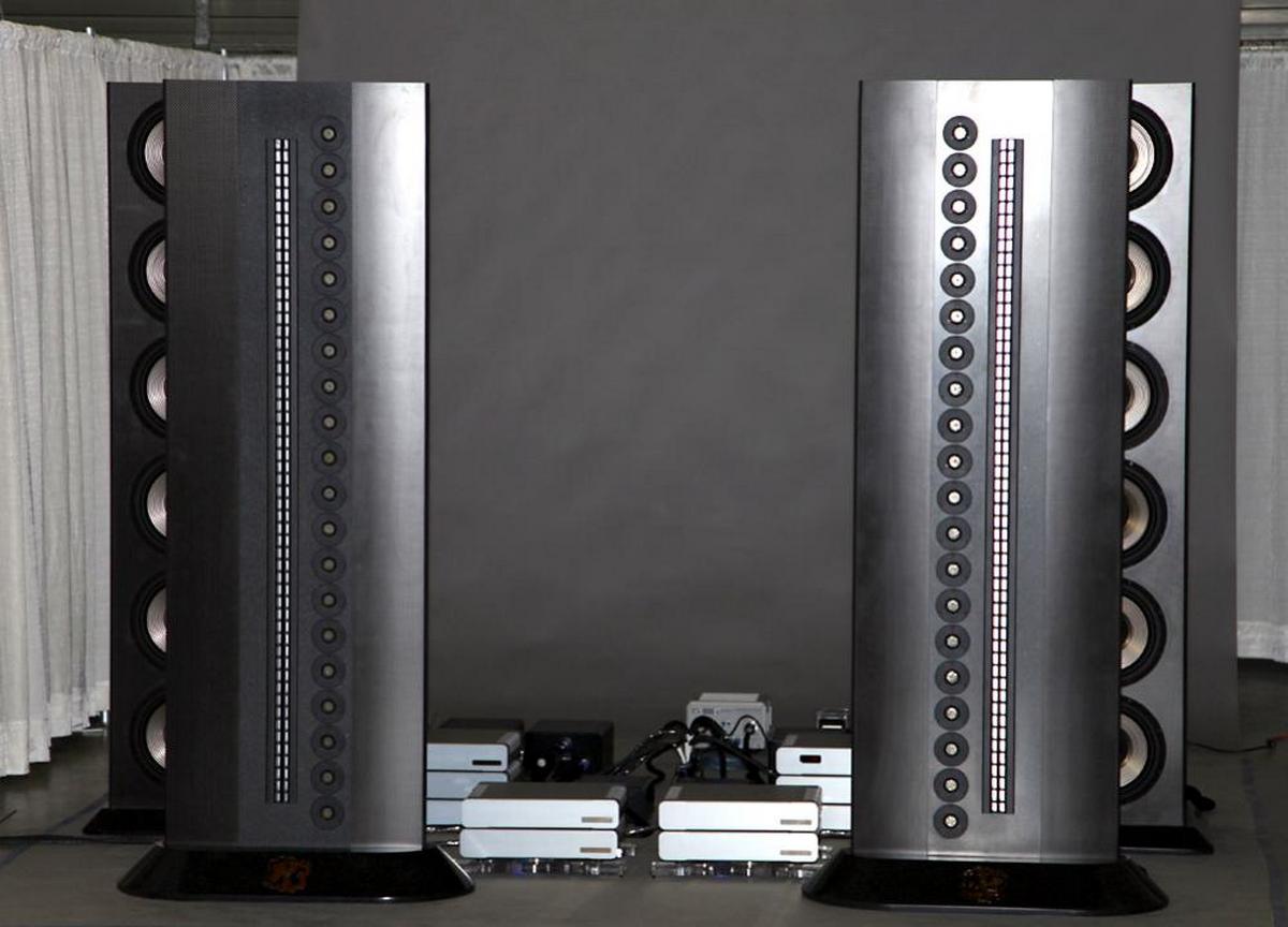
My only tweak would be to round off the corners with a liberal radius, sort of like a wide oval shape. Even then, as a free standing array it would probably struggle more to make real bass as it would have less support from the rear wall or corner.
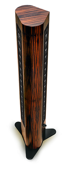
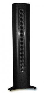
The ClairAudient line array is another interesting example:
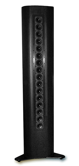
(Though this picture doesn't show the ones they have in the back sides)
Marvellous, but really expensive drivers (Audience A3, not for sale anymore, but when they were they were really expensive, like € 170.00 a piece) with lots of x-max. Not quite as flat in response as the TC9 (but close enough) and in my opinion they should have used even more drivers in that array (to make it span floor to ceiling).

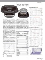
X-max (absolute) 12 mm(!) 😱. In comparison here's the TC9 under the same test circumstances:
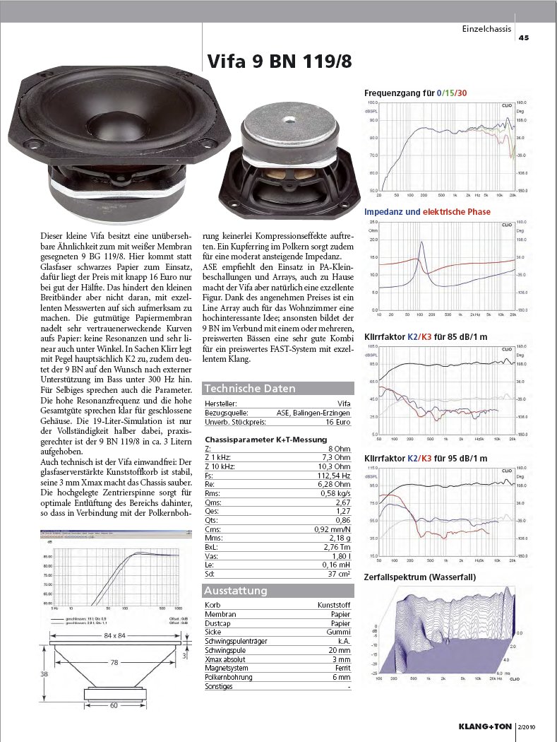
Not bad for such a cheap driver, is it? However I wouldn't say no to a box full of ClairAudient Audience A3 drivers 😀.
So it was either going narrow with wall/corner support, I deliberately chose about the size of one's head or less, or wide for a free standing array.
I'm showing I live and breath for this stuff again, I'll shut up now 😱.
The shape I would choose for a free standing enclosure would probably be much more like the Genesis full size arrays:
My only tweak would be to round off the corners with a liberal radius, sort of like a wide oval shape. Even then, as a free standing array it would probably struggle more to make real bass as it would have less support from the rear wall or corner.
The ClairAudient line array is another interesting example:
(Though this picture doesn't show the ones they have in the back sides)
Marvellous, but really expensive drivers (Audience A3, not for sale anymore, but when they were they were really expensive, like € 170.00 a piece) with lots of x-max. Not quite as flat in response as the TC9 (but close enough) and in my opinion they should have used even more drivers in that array (to make it span floor to ceiling).
X-max (absolute) 12 mm(!) 😱. In comparison here's the TC9 under the same test circumstances:
Not bad for such a cheap driver, is it? However I wouldn't say no to a box full of ClairAudient Audience A3 drivers 😀.
So it was either going narrow with wall/corner support, I deliberately chose about the size of one's head or less, or wide for a free standing array.
I'm showing I live and breath for this stuff again, I'll shut up now 😱.
Attachments


Last edited:
...I realize this is run on manufacturer's data alone but we have to have a starting point for comparison, don't we?...
Yes pure manufacture T/S data to base high pass funchtion but some of them are quite good and can start our dreaming adventures, below same datasheets response curves traced into same overlay and a third party measurement for TC9 from Zapp that confirms Vifa data is repeateable at other physical location. Doing this graph comparison makes it clear that raw out of box TC9 is king here and that 3FE22 miss its lows to keep up in sensitivity below 1kHz point.
Attachments

"In the end it worked out great."
For a "sub-optimal" enclosure, I think we can all agree it did indeed work out great!
For a "sub-optimal" enclosure, I think we can all agree it did indeed work out great!
Thanks again, BYRTT! That's quite the rising response from 7k-10k for the FSF041. I imagine that would have a rather forward sound. More evidence in favor of the TC9.
Sorry to be late on the amp question. Hypex or Ice power have all the grunt you'd ever need (I like the ice a lot). No worries there. And if these are just for ambience channels they may be overkill.
Thanks again, BYRTT! That's quite the rising response from 7k-10k for the FSF041. I imagine that would have a rather forward sound. More evidence in favor of the TC9.
A rising response in an array driver is a good thing as long as it is smooth because it needs less boost to offset the HF loss that comes along with the interaction of all the drivers.
The big peak at 8K is more of a worry though.
My TC9 array came out with a Q of 0.71 at ~2 litres per driver and the stuffing
I used, the high Qts of the driver makes that the sweet spot so I don't see the value in going bigger.
Is it even possible to get a lower system Q than the QTS of the driver used, even in the most optimum stuffed but sealed enclosure? I don't think it is.
My system Q landed at 150 Hz, while the average of all drivers measured in open air came out on 142 Hz (*), so the system Q isn't below the original driver QTS.
It did come out lower than my simulations in WinISD Pro predicted. Maybe I can find them in an old backup. So with a QTS, that's about 0.89 in the latest TC9 spec sheets, but other numbers have been reported in other spec sheets (as low as 0.72 and as high as 0.95 depending which of my spec sheets I look in, I have Rev 0 t/m Rev 3) I don't think I'm below that QTS number with the array. However I did try to get it (system Q) as low as possible trough running impedance tests and optimising damping. As that would mean lower extension in frequency, or, in other words, a little less boost needed.
(*) The drivers were tested straight out of the box, zero use or break-in time. Just a quick test to see if they were fully functional.
Last edited:
I measured the Q from a raw impedance measurement and calculated it based off of figures taken from the graph using a formula I got from Linkwitz's site. It matches the low end roll off I would expect from that Q so I am reasonably confident it is close to accurate.
It should be easy enough to take a raw array measurement and check it against a generated rolloff of Q 0.7 and 0.8 overlaid that should give a visual of what the actual real world result is.
I haven't measured the Qts of a TC9 to know which of the spec sheets is correct if any.
Having 25 in series parallel will change things somewhat electrically but I didn't test them wired out of enclosure to say exactly how.
I agree it is not generally possible to get a lower box Q than the Qts of the driver,
In your enclosure and mine there is a lot of dense stuffing right behind the driver so this could come into play.
So there could be a few reasons why the Q is different than might be expected based on the spec sheet 🙂
It should be easy enough to take a raw array measurement and check it against a generated rolloff of Q 0.7 and 0.8 overlaid that should give a visual of what the actual real world result is.
I haven't measured the Qts of a TC9 to know which of the spec sheets is correct if any.
Having 25 in series parallel will change things somewhat electrically but I didn't test them wired out of enclosure to say exactly how.
I agree it is not generally possible to get a lower box Q than the Qts of the driver,
A driver with Qts=0.8 will indeed never reach Qtc=0.707 in a standard sealed enclosure. A driver's free-air Fs and Qts can only be raised in a sealed enclosure, now convolved into Fc and Qtc.
There may be a special case, correct me if I'm wrong, where a driver with lots of dense stuffing right behind it will have its Qms lowered, by extension lowering Qts below its free-air value, but putting this in a sealed box will still only raise it from there, although Qtc could be lower than free-air Qts. Whether this can be used to good effect is another matter.
In your enclosure and mine there is a lot of dense stuffing right behind the driver so this could come into play.
So there could be a few reasons why the Q is different than might be expected based on the spec sheet 🙂
We've discussed this before! Anything you'd revise in those older comments?I agree it is not generally possible to get a lower box Q than the Qts of the driver,
PS with a sealed box and active EQ you can set the Q to whatever you want anyway 🙂
+1
Also you are probably into room modes by that frequency so all modelling bets are off.
I never worried about system Q, my only worry has been to get the impedance peek as far to the left as possible 😀.
This meant some extra work trying to find the damping scheme that was fitting to the goal of making a true full range system. The only thing I would do different today would be the wiring, I'd switch to parallel/series instead of the series/parallel I still have. This is something that won't go off of my list until I try it and learn what it brings to the table.
This meant some extra work trying to find the damping scheme that was fitting to the goal of making a true full range system. The only thing I would do different today would be the wiring, I'd switch to parallel/series instead of the series/parallel I still have. This is something that won't go off of my list until I try it and learn what it brings to the table.
I'm just guessing (and nothing new to add) but based on your guys sims it looks like you'd be able to squeeze a bit more SPL on the lower end due to all drivers staying close to equal xmax. If you are xover to subs then there probably is no point as your drivers won't be getting close to XMAX. If you are using the array with no subs then it is probably worth rewiring as it would maximize your array xmax/SPL. I could be interpreting the sims wrong though 🙂.
It isn't the only advantage, though it is true the drivers would get more even loading.
It would not be the reason for me to rewire. (and I have been running my arrays full range without subs for over 3.5 years)
My primary reason for wanting to rewire is the impedance behaviour around the impedance peak.
It would not be the reason for me to rewire. (and I have been running my arrays full range without subs for over 3.5 years)
My primary reason for wanting to rewire is the impedance behaviour around the impedance peak.
Last edited:
My primary reason for wanting to rewire is the impedance behaviour around the impedance peak.
Ah cool!
We've discussed this before! Anything you'd revise in those older comments?
Yes we have, that link shows the calculation I made on one of wesayso's graphs and I did the same on mine and got a similar result. Empirically that is the Q of those drivers in that box as measured. Whether the Q being lower than 0.89 is due to the spec sheet being off, the drivers behaving differently when wired together or the stuffing regime or something else I can't be sure.
Finally started making sawdust again...
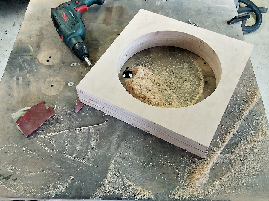
Slowly working towards this goal:

I'm keeping this simple, well... sort off. No metal frame inside. I'm making a double baffle and it may incorporate threaded rods to fix the baffle trough the enclosure at the back. Keeps it clean on the front, and easy to open up if needed. Yet it's still relatively simple to create. Only one brace to keep the body of the enclosure in its shape, and front and back fixed to each other to tighten it up.
All of this makes the subject of finding a good subwoofer amp a little more serious. I've searched for usable plate amps to keep things simple.
However, most of the A/B plate amps are too big to incorporate into a 40 x 40 x 40cm subwoofer.
Even class D amps were pretty big. One of few that could fit that enclosure without loosing much inner space was the Hypex Fusion FA501 amp. But... and it's a big but, it has a DSP module build in so it has an extra AD/DA step that I really could live without.
So that makes karsten's suggestion:
a lot more interesting! This amp is small enough (probably not that different from the Fusion amps), I'm looking at the 500 watt variant. In fact, it's small enough to fit in it's own enclosure and hang off the back of my subwoofer so I don't need to give up precious air space inside.
All I need to figure out if I go this route is how to hook it up, what connectors do I need... I don't need, or even want auto sense on. I'm perfectly happy with a switch to turn on the amps. In fact, I insist on this, as my setup is controlled by my PC and I don't want an accidental blast of sound for one of my family members. The whole setup is way too experimental for that, and will remain that way for the near future.
I've looked up the available plate amps from Ice power and all that turned up was pretty much the same deal as the Hypex fusion amp. It was the MiniDSP version with (again) the extra AD/DA conversion to incorporate DSP, sadly I found no "amp only" deals that fit my needs.
I think that OEM Hypex amp could do exactly what I want (which is simple enough). Too bad it doesn't come as a complete, good to go package. It has weird connectors that I have to hook-up, but has the advantage that I can determine where they actually go. It has a clip indicator function that I'd like to use, but for the rest I'd like to keep it as simple as possible.
An on/off switch, RCA in and speaker out. All of the rest will be done from within JRiver. Maybe the mute option would come in handy at times.
If mounted at the back of my sub I'd want the switch on top, with clip indicator and possibly a mute button, the power cord, RCA and speaker output would go to the bottom. As these subs would be pretty close to the front wall, I have about 10cm of room to play with. A plate amp would have the wires sticking out from the back of the sub, or I'd have to put it on the bottom/one of the sides. Anyway, I'd like to keep as much air volume without going larger than 40 x 40 x 40cm. So a small external amp has advantages.
Slowly working towards this goal:
I'm keeping this simple, well... sort off. No metal frame inside. I'm making a double baffle and it may incorporate threaded rods to fix the baffle trough the enclosure at the back. Keeps it clean on the front, and easy to open up if needed. Yet it's still relatively simple to create. Only one brace to keep the body of the enclosure in its shape, and front and back fixed to each other to tighten it up.
All of this makes the subject of finding a good subwoofer amp a little more serious. I've searched for usable plate amps to keep things simple.
However, most of the A/B plate amps are too big to incorporate into a 40 x 40 x 40cm subwoofer.
Even class D amps were pretty big. One of few that could fit that enclosure without loosing much inner space was the Hypex Fusion FA501 amp. But... and it's a big but, it has a DSP module build in so it has an extra AD/DA step that I really could live without.
So that makes karsten's suggestion:
Hi Ronald
I would probably go for a hypex
Hypex Electronics B.V.
for the subs and build them inside the subwoofer enclosure. These are 250W power amps with integrated SMPS and the add a signal sensing power on system. Then you dont have to worry about any WAF factor 😀
a lot more interesting! This amp is small enough (probably not that different from the Fusion amps), I'm looking at the 500 watt variant. In fact, it's small enough to fit in it's own enclosure and hang off the back of my subwoofer so I don't need to give up precious air space inside.
All I need to figure out if I go this route is how to hook it up, what connectors do I need... I don't need, or even want auto sense on. I'm perfectly happy with a switch to turn on the amps. In fact, I insist on this, as my setup is controlled by my PC and I don't want an accidental blast of sound for one of my family members. The whole setup is way too experimental for that, and will remain that way for the near future.
Sorry to be late on the amp question. Hypex or Ice power have all the grunt you'd ever need (I like the ice a lot). No worries there. And if these are just for ambience channels they may be overkill.
I've looked up the available plate amps from Ice power and all that turned up was pretty much the same deal as the Hypex fusion amp. It was the MiniDSP version with (again) the extra AD/DA conversion to incorporate DSP, sadly I found no "amp only" deals that fit my needs.
I think that OEM Hypex amp could do exactly what I want (which is simple enough). Too bad it doesn't come as a complete, good to go package. It has weird connectors that I have to hook-up, but has the advantage that I can determine where they actually go. It has a clip indicator function that I'd like to use, but for the rest I'd like to keep it as simple as possible.
An on/off switch, RCA in and speaker out. All of the rest will be done from within JRiver. Maybe the mute option would come in handy at times.
If mounted at the back of my sub I'd want the switch on top, with clip indicator and possibly a mute button, the power cord, RCA and speaker output would go to the bottom. As these subs would be pretty close to the front wall, I have about 10cm of room to play with. A plate amp would have the wires sticking out from the back of the sub, or I'd have to put it on the bottom/one of the sides. Anyway, I'd like to keep as much air volume without going larger than 40 x 40 x 40cm. So a small external amp has advantages.
Attachments

Last edited:
Raising the height a bit to have a "pizza box" amp enclosure as a base is a no-go?
Wouldn't need to be very high, as you could add a small and quiet computer fan to keep it cool.
Wouldn't need to be very high, as you could add a small and quiet computer fan to keep it cool.
The FA252 offers digital inputs & bridging in a 315mm package. Of course, your PC can handle the DSP easily, and an analog amp won't have any latency issues.One of few that could fit that enclosure without loosing much inner space was the Hypex Fusion FA501 amp. But... and it's a big but, it has a DSP module build in so it has an extra AD/DA step that I really could live without.
You are always a couple of steps in front of me. I have to finish my work on expanding the DAC and the volume control to 4 channels before I start making sawdust.
One of the nice things with the Hypex combined amp and SMPS is , that the standby power is very low, so you only have to mute the amp instead of having a power switch, no matter what solution you chose (automatic on or a dedicated switch).
One of the nice things with the Hypex combined amp and SMPS is , that the standby power is very low, so you only have to mute the amp instead of having a power switch, no matter what solution you chose (automatic on or a dedicated switch).
- Home
- Loudspeakers
- Full Range
- The making of: The Two Towers (a 25 driver Full Range line array)