Are you dead set on using another sheet of aluminium for the last piece of the baffle?
If not, how about getting a sheet of transparent plexiglass? You would still get the color and feel of the alu panel underneath, but I know for a fact that a router cuts through plexiglass like butter!
I'd like to keep it Aluminium with mass loaded vinyl inbetween the front and rear baffle. I bet cutting plexiglass with these speeds would make a mess too!
Just buy no name router with speed control, it should be cheap.
I've had one of those... it lasted a whole week with the work I did with it... it literally collapsed after that week of work. A speed limiter would cost about the same but it would let me keep using my decent router...
I should be save running at ~10000 RPM... I'll update when the limiter arrives.
Find a broken variable power vacuum cleaner and reuse the speed control board
That's not a bad idea at all! 🙄
"Just thinking", aren´t you trying to cut too much material at once?
I think I am, the next baffles I will cut a bit wider with the jigsaw.

Absolutely beautiful work. The attention to detail (external AND internal shape looked after, choice of baffle material, construction method, etc.) makes it closer to an actual marketable product rather than just a DIY project.
I notice that some of the drivers made for line array have big magnets that are quite close in diametre to the overall diametre. Is it okay for the magnets to be within millimetres of each other?
I notice that some of the drivers made for line array have big magnets that are quite close in diametre to the overall diametre. Is it okay for the magnets to be within millimetres of each other?
Thanks for the compliments!
I couldn't tell you if mounting the magnets close to each other would have severe detrimental effects but I would worry about the airflow of the back wave with such big magnets. I'd guess they would suffer from more back wave reflection trough the cone.
I remember reading the comments from Overkill Audio on the BMR drivers with ferrite magnets (those magnets are almost the same size as the cone) having a very closed in sound. He uses Neo magnets on his own OEM line of BMR's for a more open sound.
One of the reasons for my baffle construction is to ensure good flow of air at the back of the driver. I wanted to minimise the thickness as to not create a "tunnel" in a thicker baffle. The magnet on the TC9 driver is smaller than the spider so it should be OK in that regard.
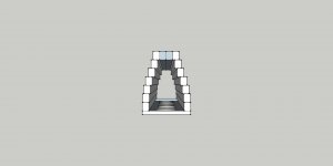
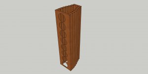
You stacked pieces from bottom to top, but I'm wondering about stacking them from front to back.
Once assembled, I could sand the exterior and make a smooth curve, while keeping the interior irregular.
Here's a crude, not to scale and not with the right amount of drivers, of my idea.
Once assembled, I could sand the exterior and make a smooth curve, while keeping the interior irregular.
Here's a crude, not to scale and not with the right amount of drivers, of my idea.
Attachments
I would imagine gluing them up and keeping them straight for a 2 metre tall enclosure would be quite a troublesome task. But fabricating the individual pieces is a lot easier, and for shorter line arrays it would be easier.
Or maybe you have something in mind that the sketch doesn't show?
Or maybe you have something in mind that the sketch doesn't show?
There would be internal bracing that is not shown in the drawings.
I know that keeping the whole thing straight and not warping would be the biggest challenge.
Maybe doing it in stages, just like a rocket. Depending on the number of drivers I go with again (between 16 and 25) I could do 4 or 5 sections that would be stacked and glued up in the end.
That would also be easier to do at home, since space is limited... and so it the wife's patience for my multiple hobbies!
I'd love to see that.
If I am building one I'd just make the internals straight and be done with them. 😀 Though I have some ideas of my own. Nothing innovative, just to make wiring and servicing the array a lot easier.
If I am building one I'd just make the internals straight and be done with them. 😀 Though I have some ideas of my own. Nothing innovative, just to make wiring and servicing the array a lot easier.
The continuation of my struggle...
After breaking several more bearings I figured I needed to take another route.
I first tried a device to regulate the speed of my router. The device works like a charm but it didn't solve my problem entirely.
After cutting the second baffle with slightly bigger pre-holes using the jigsaw it seemed promising, but after cutting 4 holes with one bearing (a damaged one even) the next holes didn't go that well, costing me again several bearings and rougher end results due to the exploding bearings 😱. I didn't feel that save to, wearing eye protection and gloves but sometimes parts of the bearing would just shoot off the table.
The advise I got from you guys kept ringing in my ear. Especially the one about using copy rings. I figured why not make a follow pin for the template
above the table instead of needing new templates for a copy ring. (as it doesn't need to be a bearing with the slow movements the pin sees).
But it needs to be sturdy enough attached to the router table to withstand the pressure you put on it in all directions.
I had a few threaded bushings from an old couch that was the same diameter as the bearings I used. So I gathered some material I had on hand and came up with this:

Zoomed in a little closer:

You can see the bushing just covers the top part of the router bit where the bearings usually ride. The angle iron is bolted to the table using some scraps as spacers and is firm enough. I welded on an extension to keep it stable in all directions.
This solution works very well, I am still spraying the WD-40 to keep the aluminium from clinging to the bit and for cooling. I now work at about half the rotational speed and did several holes without problems. This gives me the insurance I can even use this method for the outer baffle, even with the fancy fillets.
After breaking several more bearings I figured I needed to take another route.
I first tried a device to regulate the speed of my router. The device works like a charm but it didn't solve my problem entirely.
After cutting the second baffle with slightly bigger pre-holes using the jigsaw it seemed promising, but after cutting 4 holes with one bearing (a damaged one even) the next holes didn't go that well, costing me again several bearings and rougher end results due to the exploding bearings 😱. I didn't feel that save to, wearing eye protection and gloves but sometimes parts of the bearing would just shoot off the table.
The advise I got from you guys kept ringing in my ear. Especially the one about using copy rings. I figured why not make a follow pin for the template
above the table instead of needing new templates for a copy ring. (as it doesn't need to be a bearing with the slow movements the pin sees).
But it needs to be sturdy enough attached to the router table to withstand the pressure you put on it in all directions.
I had a few threaded bushings from an old couch that was the same diameter as the bearings I used. So I gathered some material I had on hand and came up with this:
Zoomed in a little closer:
You can see the bushing just covers the top part of the router bit where the bearings usually ride. The angle iron is bolted to the table using some scraps as spacers and is firm enough. I welded on an extension to keep it stable in all directions.
This solution works very well, I am still spraying the WD-40 to keep the aluminium from clinging to the bit and for cooling. I now work at about half the rotational speed and did several holes without problems. This gives me the insurance I can even use this method for the outer baffle, even with the fancy fillets.
Your persistance pays off in spadesThe continuation of my struggle...
After breaking several more bearings I figured I needed to take another route.
I first tried a device to regulate the speed of my router. The device works like a charm but it didn't solve my problem entirely.
After cutting the second baffle with slightly bigger pre-holes using the jigsaw it seemed promising, but after cutting 4 holes with one bearing (a damaged one even) the next holes didn't go that well, costing me again several bearings and rougher end results due to the exploding bearings 😱. I didn't feel that save to, wearing eye protection and gloves but sometimes parts of the bearing would just shoot off the table.
The advise I got from you guys kept ringing in my ear. Especially the one about using copy rings. I figured why not make a follow pin for the template
above the table instead of needing new templates for a copy ring. (as it doesn't need to be a bearing with the slow movements the pin sees).
But it needs to be sturdy enough attached to the router table to withstand the pressure you put on it in all directions.
I had a few threaded bushings from an old couch that was the same diameter as the bearings I used. So I gathered some material I had on hand and came up with this:
Zoomed in a little closer:
You can see the bushing just covers the top part of the router bit where the bearings usually ride. The angle iron is bolted to the table using some scraps as spacers and is firm enough. I welded on an extension to keep it stable in all directions.
This solution works very well, I am still spraying the WD-40 to keep the aluminium from clinging to the bit and for cooling. I now work at about half the rotational speed and did several holes without problems. This gives me the insurance I can even use this method for the outer baffle, even with the fancy fillets.

Nice work. I often use rub collars when using the shaper.
I admire your ability to stay with a project.
I admire your ability to stay with a project.
Thanks guys...
I must say I enjoy this forum very much. There always is a lot of positive feedback and it sure helps to motivate.
Here's the first two baffles:

A lot more needs to be done to them (on the back side) but this will do for my immediate next step, fixing the enclosures. I needed the baffles for that.
Don't expect me to be done in a few days yet 😀.
If I learned one thing from this project it is to be patient.
I'll have to sand down that nice finish I got to be able to get something usefull. Too bad, but I'll pick up the original plan to have an epoxy/matt outer shell on them. Time will tell how that step goes. Sadly I'm running a bit behind my original schedule because my car (from 1982) was in need of repairs.
The car is fixed and running great again so I can go back to this project full force.
Glad the aluminium machining is now working well. That gives me the opportunity to make it just as I had planned. All done with simple wood tools so it will still take a lot of time.
I must say I enjoy this forum very much. There always is a lot of positive feedback and it sure helps to motivate.
Here's the first two baffles:
A lot more needs to be done to them (on the back side) but this will do for my immediate next step, fixing the enclosures. I needed the baffles for that.
Don't expect me to be done in a few days yet 😀.
If I learned one thing from this project it is to be patient.
I'll have to sand down that nice finish I got to be able to get something usefull. Too bad, but I'll pick up the original plan to have an epoxy/matt outer shell on them. Time will tell how that step goes. Sadly I'm running a bit behind my original schedule because my car (from 1982) was in need of repairs.
The car is fixed and running great again so I can go back to this project full force.
Glad the aluminium machining is now working well. That gives me the opportunity to make it just as I had planned. All done with simple wood tools so it will still take a lot of time.
Last edited:

- Home
- Loudspeakers
- Full Range
- The making of: The Two Towers (a 25 driver Full Range line array)