Hello everyone
After some private message requests for the manufacturing files and Sprint Layout, I decided to make them available for everyone.
On the images the name 'KEANTOKEN' has a small error and it is repaired in the attached files in the archive.
The first version I made and hand made that works perfectly is visible here but I made some small aesthetic and practical changes.
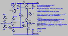
The Kuartlotron - keantoken's simple error-correction superbuffer
Regard's
After some private message requests for the manufacturing files and Sprint Layout, I decided to make them available for everyone.
On the images the name 'KEANTOKEN' has a small error and it is repaired in the attached files in the archive.
The first version I made and hand made that works perfectly is visible here but I made some small aesthetic and practical changes.
The Kuartlotron - keantoken's simple error-correction superbuffer
A small production of 10 printed circuits is launched and I will have two to three pairs available in some time.Interested, if some boards are available.
Regard's
Attachments
I used thisl one with a 10k pot at the input.
That is a buffer, not a LP filter. What did you do to make it a LP filter? You may just need to remove the 10k resistor.
Hi Kean , thank you. Sorry I wasn't clear enough.Your schematic in post 921 it is just what I used in the LP active crossover , except L1 and L2 and 1M shunt input resistor . My question was about the buffer used as preamp with volume control, not the buffers used in the active crossover.
Okay. Well that is interesting, since it's the first time I've heard of a problem with the bass. The boards I sell use a 100k input resistor, the original circuit used 10k because some early users wanted to use it DC coupled. If you are using an input capacitor try using 100k instead of 10k.
Hello everyone
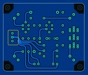
Visibly a small trace poses problem for some manufacturers with the track connected to the ground plane, so I modified the layout to correct this problem.
😉
Visibly a small trace poses problem for some manufacturers with the track connected to the ground plane, so I modified the layout to correct this problem.
😉
Attachments

Hey Project16, do you still have boards available for this? How much of an issue is 12V in, or should that be dropped to 10V?
I know the pcb design programs are designed for production assembly, not diy and this is a bit late in your design procedure but is it possible to increase the size of the donuts and also the space between the donuts and the surrounding 'planes?
As it is, the small donuts and narrow clearances increase the chances of a 'short' plus when altering components, it's rather difficult to avoid board damage
As it is, the small donuts and narrow clearances increase the chances of a 'short' plus when altering components, it's rather difficult to avoid board damage
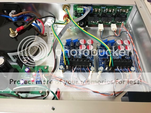
Built up one of project16s boards tonight. Adjusted to 5v at TP but encountered something odd: r9 trimmer did nothing to the offset but I could dial it down with r1 trimmer. Is this normal?
Will measure fft with rew next but that’s for another day.
Will measure fft with rew next but that’s for another day.
If you did it with the input grounded, then R9 will not do anything. It needs to be adjusted with the input open. R1 is for trimming distortion, not offset, although you could use it that way for small amounts of offset if distortion wasn't particularly important.
Ok, had another go at this. With open inputs the offset is 45mv, r9 is a 1M trimmer paralleled with 1.8M. I can adjust approx 10mv across its whole range. I suppose I need to change R9 to something else but I’m unsure what.
Vbe of 560s were 0.686 and 0.688 and 550s were 0.685 and 0.680.
Vbe of 560s were 0.686 and 0.688 and 550s were 0.685 and 0.680.
Ok, had another go at this. With open inputs the offset is 45mv, r9 is a 1M trimmer paralleled with 1.8M. I can adjust approx 10mv across its whole range. I suppose I need to change R9 to something else but I’m unsure what.
Vbe of 560s were 0.686 and 0.688 and 550s were 0.685 and 0.680.
Hello Silas
R9 is a 1M trimmer with a 1.8M resistor in series and not in parallel.
😉
Ok progress, I switched the 1M pot for a 5k one and jumpered the series resistor position and managed to get below 1mV. Not sure how to explain this, I clearly misread the schematic and thought r9 was 2k7...
Kean, they are 560CTA.
Kean, they are 560CTA.
Last edited:
Ok, using the 1M trimmer with the series 1.8M also works, so I suspect I’m just at the end of the travel for the pot, probably at low R. Would it make sense to try something even higher, like 2.2M for the Series resistor to R9? Is Avery low resistance for R9 a problem?
The values 1M for the trimmer + 1.8M for the resistance correspond to the schematic.
If the trimmer is at its maximum value I think that a 2.2M should solve the problem but maybe it is at its minimum value and at that moment it is necessary to reduce the value of the resistance.
Keantoken may be a suggestion.
If the trimmer is at its maximum value I think that a 2.2M should solve the problem but maybe it is at its minimum value and at that moment it is necessary to reduce the value of the resistance.
Keantoken may be a suggestion.
Yeah I think it’s at min value, so essentially r9 is jumpered. Not sure what to make of it. On start up, tp slowly goes to 5v and offset to1-2mV.
- Home
- Source & Line
- Analog Line Level
- The Kuartlotron - keantoken's simple error-correction superbuffer