
I'm working on diferent aproach, direct digital power dac DDPD, pdm modulated, variable power supply as a volume control, want to hear opinion, thank you! Measurement results was not very good but sound was very huge and dynamic. -> https://www.diyaudio.com/community/threads/direct-digital-power-dac-ddpd.395974/
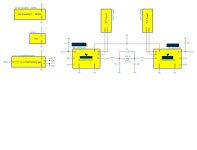
In attachment is new design based on gan fet in full bridge configuration, the same concept with variable dc power supply as a volume control. Picture 2 is idea for their FB. The idea in mind about FB is 1bit pdm feedback bitstream similar to input bitstream, diferentiating input and fb and create 32bit error pattern which will auto manipulate bits on input bitstream. thats an idea in mind.
In attachment is new design based on gan fet in full bridge configuration, the same concept with variable dc power supply as a volume control. Picture 2 is idea for their FB. The idea in mind about FB is 1bit pdm feedback bitstream similar to input bitstream, diferentiating input and fb and create 32bit error pattern which will auto manipulate bits on input bitstream. thats an idea in mind.
Attachments
Last edited:
iRiver Astell&Kern AK120
There should be width and depth. Some people also perceive height, but stereo recordings don't carry cues to height perception. It may be some people still perceive height possibly associated with higher frequencies. For example, a forward-of-the-speakers and narrow-between-the-speakers sound stage may also sound kind of up in the air where higher frequencies emanate from the HF speaker drivers. That type of forward and narrow sound stage IME usually indicates a clock jitter issue.
perceive height possibly associated with higher frequencies
Yes, high frequencies often seem to come from above the head. Sometimes, I feel the bass around my shoulders. However, unfortunately, when it comes to depth, there wasn’t any mutual agreement during the listening evaluation with my friends. but, with certain music, I’ve felt surrounded by the sound, especially by the bass in the background.
Thanks!
thank you for sharing with us, and congratulations on your achievement.direct digital power dac DDPD
I was thinking to use this solution at the beginning of the project, but I gave up quickly because of several reasons as below:
1, many factors, such as dead time, high side and low side mismatch, clock jitter, ground bouncing and so on, generate significant distortion.
2, difficult to control DC offset.
3, volume control problem.
4, no PSRR, need a pretty clear power supply.
I recommend that using a local PLL to lock the clock of the DSD signal and then use a D latch to reshape the signal may reduce some clock jitter.
FB is quite novel and interesting idea, good luck!
This one looks promissing for 1bit fb concept? Can be synchronised with dsd clock too. https://www.ti.com/lit/ds/symlink/opa615.pdf
Last edited:
yes, it is. however, please check it carefully, higher speed sometimes come with lower resolution.
I am not fully understood your 1-bit FB system, my understanding is the error is the time difference, so you have to have a circuit to implement the time shifting to realign the output and input signal with certain designed delay (the delay may impact the stability of your system), which can be integrator and comparator or digital counter.
if I were you, I would like to use a high-bandwidth linear AMP with FB (class AB?) to amplify the PDM signal with lost some efficiency. but a lot of benefits, such as no deadtime distortion, lower DC offset, high PSRR etc. but, the high-bandwidth linear AMP is a Challege. the basic BW of DSD64 is about 1.4MHz, it still doable.
BTW, DSD digital output signals may not always ensure accurate timing for the rising and falling edges (digital system has high tolerance of clock jitter). A good approach is to first generate a complementary signal, then lock it using a D latch synchronized with a high-precision local recovery clock.
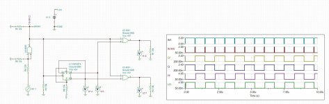
I already suspected that something was wrong with the input, at first I thought I put an insufficient number of buffers, but later I tried to remove the half-bridges and leave only a sufficient number with each buffer, get identic bad result. There is an RCD placed on the complementary hi and lo, through which a tenth of ns is obtained for the dead time, but neither helped. I will definitelly think about reclocking input, And it would be probably need with the variable dutty, one for first HB and seccond one for for seccond HB, for controling DC offset somehow. Thanks!
E.g. controling height of the square by increasing or decreasing dutty of the IN1, something like this. That way dead time can be controled too. Probably an clocking with variable dutty close to 99% will be need.
E.g. controling height of the square by increasing or decreasing dutty of the IN1, something like this. That way dead time can be controled too. Probably an clocking with variable dutty close to 99% will be need.
Attachments
Last edited:
I would like to say trying to control the pulse width of the DSD signal may not get what you want. the high resolution of DSD modulation comes from the technique called Quantization Noise Shaping rather than over-sampling only. the technology moves the quantization noise from audio band to high frequency. the final quantization noise spectrum is determined by the feedback transfer function. if trying to change the duty cycle may change the equivalent transfer function and move the quantization noise back to audio band. of course, you also have chance to have a better equivalent transfer function, and higher resolution.
Last edited:
I not meant to modify dsd I meant to modify pulse width of the complementary hi, lo. See picture above, IN1 would be dsd bit 1 or 0 for example, by something like this we would have changeable duty from 0 to 99 to IN1 and the same time control for dead time between hi and lo. Having this for example on booth half bridge we probably can have asymetric mechanism for controling dc offset too by that asymetric hi,lo
Last edited:
This would be the concept of complementary HI and LO from the picture. We would have to design a reclocking mechanism so that each dsd bit produces this IN1 signal, but from that we would only use either HI or LO but make this circuit double, meaning one would be for one half-bridge and the other for the other half-bridge so that we have the option to create asymmetry through two different duties, one half-bridge and the other half-bridge, thus we would have control over both the DC offset and the dead time at the same time. It's not that simple, the clock would have to be x2 so that the resulting HI or LO would be at the same dsd frequency!
Attachments
Last edited:
FB concept idea, not literally the same as marked green but similar to that.
Attachments
Last edited:
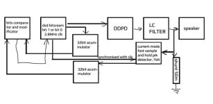
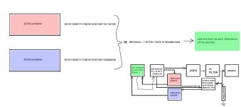
FB needs to recover the lost bit resolution after the lc filter, speakers and speaker cable, to subtract or add those missing bits to the input dsd based on the error-difference in the bits, that's the idea. In practice correction will work on 2.8MHz / 32 = 87.5KHz. Both containers would accumulate bit by bit until the containers were filled with 32 bits, all at the DSD clock frequency.
Last edited:
Ok, for FB solution, to be honest, I don't think it works, if I catch your idea correctly, the reasons are:
1, 32 bit accumulator will introduce too much delay, don't know the FB loop is stable or not, and why 32?
2, how sample and hold can output 1 bit, without integrator the quaternization noise is too high.
3, Apply an ADD operation on DSD signal with 32 bit long, I don't think DSD signal support that, it will destroy the original noise shaping design.
the HI and LO is generated from DSD input with deadtime control, right? modify the HI and LO pulse width is modify the pulse width of DSD signal, as I understanding. let me know if I am wrong.I not meant to modify dsd I meant to modify pulse width of the complementary hi, lo.
Pulse heigh need to introduce the right dead time between hi and lo, not too much and not too litle but optimal so that H bridge get their optimum switching. e.g. 5ns of dead time.
1. It can be 8bit too for example, my choice for 32bit is to get a bit more resolution for error in order to determine the right error mask for add/subtract operation
2. please see figure 46 https://www.ti.com/lit/ds/symlink/opa615.pdf , circuit for fb need to be simple, to pickup voltage from the shunt and keep them in hold, on next dsd clock to pick another sample and make diference between sample 1 and sample 2, sample 1 > sample 2 = output LO, sample 1 < sample 2 = output HI. Store bits to acumulator.
3. see working add operation https://www.diyaudio.com/community/threads/1bit-dsd-bitstream-mix-possible-yes.402025/ bits modification is definitelly possible, but what I want to do is similar but not to convert to dsd128, instead to modify dsd input bits based on error mask so that at the fb I have original dsd or close to original. I don't know if that have sense?
Note that this is just idea, I don't know if this will work at all, I want to try, to be honest just want to store fb bits and dsd bits into two containers on storage and do bits analize, and if there is some sense then I'll think further.
Last edited:
Number 1: Assuming the output after the LC filter has zero distortion, the sample-and-hold circuit continues to output the 1-bit stream. I believe this stream differs from the original DSD signal (DSD modulation is not unique solution system), meaning the difference is not zero. However, under the given assumption, this difference should be zero.
Number 2: Assuming there is distortion, but its amplitude is not big enough to change the relationship "sample 1 > sample 2," the 1-bit output will remain unchanged, and the error will not be corrected.
Number 2: Assuming there is distortion, but its amplitude is not big enough to change the relationship "sample 1 > sample 2," the 1-bit output will remain unchanged, and the error will not be corrected.
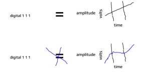
Yes its definitely hard to even think about it, diference is probably totaly diferent in relation to bit to bit comparation, and also diference between amplitude level from the input-output is definitely not the same. Previous idea was to connect an pga with volume control circuit since idea is to use variable power supply as a volume control so that input,output get at the close amplitude level, than to use an sigma delta adc...etc. But I got diferent idea, above. Idea is: what does digital 1 or digital 0 at the input,output? In my point of view digital 1 just changes aplitude up at speaker and digital 0 changes amplitude down at speaker, my idea is to put an simple pik detector to track those up-down amplitude changes at the speaker so that if at the input is digital 1 and if at the speaker is digital 0 eror is digital 1, imediatelly to make next digital in = 1, or vice versa. Call this simple io to io comparation, or pik to pik comparation. Since dsd is an fixed freq modulation it might work this way? Does it have sense?
Idea to use 32 bit containers is for debuging purpose, to plot and compare booth containers for getting idea about what diference is between those two 32bit containers and later eventualy get an idea about what can be possible to do in relaton to fb.
Idea to use 32 bit containers is for debuging purpose, to plot and compare booth containers for getting idea about what diference is between those two 32bit containers and later eventualy get an idea about what can be possible to do in relaton to fb.
Last edited:
The most difficult part is to make this sample-and-hold peak detector so that it is able to accurately compare the value from the "hold" with the value from the next "sample" and produce a digital 1 or a digital 0 based on the "sample-and-hold". I have no idea which one to chose for this, maybe with opa615 or something better?
Edit: sorry google translate. Pik = peak!
Edit: sorry google translate. Pik = peak!
Last edited:
- Home
- Amplifiers
- Class D
- The Journey of DIY No-Feedback Class D Amplifier (1) Subtitle: The Motivation and Story Behind It