Had a lot of fun with the SP-10mk2a this morning adjusting offset voltage, RS current and sync positions trying to get a response like in JP's video.
Lowering offset voltages increases overshoot but too much & you loose sync. Too much offset voltage and the motor waves gets chaotic. This video shows where I wound up. I still can't start at 33 and get it to sync. I have to go up to 45 then down to 33. I tried experimenting with the RS current setting & didn't have any luck.
I just ordered caps. Could that possibly be the issue?
Thanks
Offset changes sync, so you need to set sync after. If it falls out while setting offset then tweak sync so that it doesn’t
Can’t see video - poor connection in this Bath pub.
Can’t see video - poor connection in this Bath pub.
Yeah, getting the sense that it's like biasing a power amp - bias current then DC offset, then back to bias current... Thanks for sharing your knowledge and the videos have been very helpful. My video is a little ragged. I assume it's compression because it looks a lot better on my PC. I'll do a couple more iterations on the SP-10.Offset changes sync, so you need to set sync after. If it falls out while setting offset then tweak sync so that it doesn’t
Went back over sync position & offset & now it will sync at all speeds from stopped. This video looks better than the last one.
Thanks again for all the help!
Thanks again for all the help!
That looks great!! Nicely done. 🙂
You’re going to LOVE the SP-10.
You’re going to LOVE the SP-10.

Where’s the notch in the sync waveform? Zoomed in too far to tell but it looks off. That scope has cursors doesn’t it?
We’ll see what it looks like after the motor service - the spike on the drive waveform is quite larger than we’d want.
We’ll see what it looks like after the motor service - the spike on the drive waveform is quite larger than we’d want.
In the UK ?Ha I’m in another pub with crap data. Proper dogs, though.
Sorry, no cursors. The notch is at approx 8.5ms - I shifted it to the left so that it lined up to the grid making it easier to see the overshoot.Where’s the notch in the sync waveform? Zoomed in too far to tell but it looks off. That scope has cursors doesn’t it?
I tested W&F again with the Feickert software & test record & it improved from .09% to .04% and the vibrations are gone, I think.
I probably won't get the motor until next weekend.
Hopefully this can be of use to someone.
I made this full scale drawing of a plinth for my SP-10mk2A. I would suggest you experiment with the arm board holes because they didn't work well or ideally for a couple of my tonearms. The drawing is to scale so if you can make a full size print, it should make hole layout easier. It can also be used for a laser cutter or CNC machine because it's vector. Pay no attention to the dust on my DAC, it's not getting much use these days.


I made this full scale drawing of a plinth for my SP-10mk2A. I would suggest you experiment with the arm board holes because they didn't work well or ideally for a couple of my tonearms. The drawing is to scale so if you can make a full size print, it should make hole layout easier. It can also be used for a laser cutter or CNC machine because it's vector. Pay no attention to the dust on my DAC, it's not getting much use these days.
Attachments
We are about 2 1/2 hours away if you want to come down to Devon & Cornwall next time ?
Considered the possibility this trip but you seemed a bit distant for a day trip. Let’s connect next time - I generally visit 2-4 times a year.
No - I’m on my third retirement. Just visiting friends. My wife has meetings in London and tomorrow is her 50th, so a visit seemed sensible.
I acquired a SP10 mk2 earlier this year without a power supply.
Last weekend I finally finished building my "alternative" power supply with a small 5V linear power supply with Ian Canada's Ultracapasitor Pro board on the 5v supply (Output measuring 4.97v), and a Meanwell switch mode supply for the 32.5v.
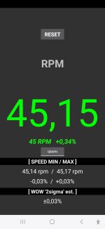
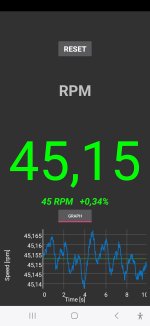
I measured the speed, wow & flutter with the RPM and WOW app, and all measurements are just above the indicated speed by 0.2 to 0.3%.
I hooked up my small oscilloscope and didn't get any change in phase tracking when adjusting VR101 and VR102 on the 33, 45 or 78rpm. Only shudder when going too far off the "base setting".
I tried again the day after and then the unit responded to the adjustments without the shuddering.
I adjusted the 33 and 78 rpm phase adjustments correctly, but the 45rpm (which have no adjustment) doesn't align to 4.7ms. I get a reading of 5.5ms.
What influences the 45rpm phase alignment signal? How can this be adjusted?
When I power down the power supply I get a violent kick (video below). I get the same movement if I pull the cable out of the power supply.
What can give the short kick in movement when powering down?
Somethings tell me I need to bring out the soldering iron and start changing all the capacitors that arrived some time ago...
PS. Updates are needed to the power supply switch on the front. In the future I need to keep power on to the 5V linear power unit to ensure the capacitors are charged when in standby. Only use the power switch at the back of the unit when I want to power down the complete unit.
The large capacitors takes a few minutes (10+min first time) to charge back to full power since my 5V linear power supply only deliver 1.5A.


As I said on Facebook do not believe your app.
Also if you look at the original PSU you will find a time sequence dependent switch on/off
I don't understand why changing capacitors instead of locating the fault is a good idea ?
Also if you look at the original PSU you will find a time sequence dependent switch on/off
I don't understand why changing capacitors instead of locating the fault is a good idea ?
- Home
- Source & Line
- Analogue Source
- The Incredible Technics SP-10 Thread