My interest in having a SP10 MkII produced to function as a version of a Kaneta Design has now come to fruition.
I have very recently seen a Video sent by a friend of my Donor TT in a New Plinth, where the OEM design is stripped of its Metal Chassis and PCB Electronics.
The off board electronics for this design is functioning and producing both 33 and 45 rpm for the TT to run at.
Hopefully by early in the New Year this will have been demo'd to myself and a few others, using the same Tonearm and Cartridge, as an A/B comparison to a SP10 Mk II mounted in a P'holz Plinth.
There are also available to be tried out, a selection Platter Types with alternate Materials used for the Platters production.
The experience of this alternate design for the SP10, will allow for work undertaken by others which is already documented within this thread to be simulated.

Yes let's see! I have seen a few re-housed MK2's but all are a bit cantankerous and put me off attempting to do so myself. But... one does need a new project!
Hopefully by early in the New Year this will have been demo'd to myself and a few others, using the same Tonearm and Cartridge, as an A/B
Are you going to do some laybacks so comparisons with basic controls might be done?
In the short term, the intention is to have a day out to a friends home, where a small group of well seasoned SP10 MkII users are to get together and experience the version of a Kaneta design in use, it has been a talking point for quite a period of time.
As stated the controls to be used on the day will be a same Tonearm and Cartridge used on the SP10's.
I am keen to pick up on the responses from the listeners. If I was to presume a avenue of thought to occur, I would expect the use of Densified Wood for the Kaneta will be suggested as one of the next steps, as the use of densified wood on this OEM SP10 Mk II has shown itself to be very attractive as a selection for a material and has been adopted as the material of choice by all who will be in attendance.
I have an SP-10 MK2P which has been overhauled and works well. As I intend to use a kaneta style plinth I would like know who in the UK sells suitable high quality densified plywood.
Thanks in advance.
[In my case ALL function controls are on the facia of the rack mounted power supply which contains all motor control electronics - just the motor and arm on the plinth.
I instructed a local cabinet-maker some months ago to make a plinth from best quality birch ply....as he has really got no further than cutting out the centres and rough sawing the externals I have cancelled the instruction and paid for the wood used]
Last edited:
What arm and cartridge might you be using ?As stated the controls to be used on the day will be a same Tonearm and Cartridge used on the SP10's.
The Tonearm will be a PMAT1010, which is the host of the 'get together' bespoke produced model and also the Tonearm adopted for use by all individuals in the group who will be attending .
The main used Cartridge on previous meets is the Windfeld and is most likely to be used on this occasion, this Cartridge will be used for the bulk period of the listening. There are other options that are able to be introduced as well if time allows.
As a side experience, an AN IO is one possibility, a rebuilt Kontrapunkt C with a few design tweaks is another, occasionally a rebuilt Kontrapunkt B with a WRD and Beryillium Cantilever > Ogura Vital is used as well.
The Cartridges are available pre-mounted in the same Headshell Type, which makes swaps between models easy with little time lost.
These introductions between friends to demo' working prototypes / present new ideas, are always fundamentally social and about being in the company of others with a shared interest, if good impression is made, then a seed is planted, to see where concepts for evolvement may be directed.
OK, providing the rest of the system is of similar quality then you should be good to go. I would try many different types of music. It could be an all day job !
Amy chance of a photo or two now ?
Amy chance of a photo or two now ?
Hi Dave
The TT is at a friends about 60 miles from my home, I have not got immediate access.
I will get images on the day of meet.
I do have a video which was sent, and tried to screenshot stills from it but failed to download the captures.
The TT is at a friends about 60 miles from my home, I have not got immediate access.
I will get images on the day of meet.
I do have a video which was sent, and tried to screenshot stills from it but failed to download the captures.
I tried a different method to extract frames from the video, Voila.
The Armboard is CNC produced from Corian.


The Armboard is CNC produced from Corian.
This work is the latest of a selection of other designs for audio equipment that are being produced in deepest East Anglia.
I am not familiar with the above referred to audio devices when visiting the homes of friends.
This design is on the table as a result of the meet up's had with the same company, prior to the meet being arranged for the very near future, the options that can be used for the SP10 MkII are the Cornerstone for this as a design.
After the initial experience and day of socialising, hopefully at some point on the future this design is be put to the test under the watchful eye of an individual who is known in the UK for their knowledge of the SP10 MkII.
'If' the electronics utilised are proved to be on par with what is known to be achievable, the mechanical interfaces that can be put in place, I am sure will be pondered.
For myself, the period of waiting, to be followed by seeing the design Powered On and working with a Platter rotating at 33 and 45 rpm is plenty to get myself full of enthusiasm.
Looking forward to the results of the meeting of like minded souls as to how the work has changed how the SP10 now functions and sounds.
Hope it goes well and all involved have a great meet.
Hope it goes well and all involved have a great meet.
Hi everyone,
I'm facing an issue with the speed of my turntable. Initially, the speed began to run away, going faster than 78rpm, and the speed selector stopped functioning altogether.
I've replaced all the capacitors and rectifiers in the power supply and calibrated it using a second (working) SP10. I also replaced C2, C4, C6, and all the capacitors on the logic board, as some of them were leaking. However, this did not resolve the issue.
I later discovered that one of the FG coils had infinite resistance. The defective coil had 510 windings, so I rewound it using 0.1mm enameled copper wire. Since I don't have specialized tools, I used my cordless screwdriver to do this – and it was certainly not an easy task.
In the end, I managed to get 310 windings on the coil before it was full. I measured the resistance on the original, working coil (200 ohms) and the rewound coil (100 ohms). I decided to test it anyway, and although it didn’t fully fix the issue, it improved the situation. The speed selector is now functional, and the speed is more stable, though still not perfect.
I'm not sure how to proceed from here. Should I try using a thinner wire to match the resistance of the original coil, or should I rewind the original coil to ensure both have the same 100-ohm resistance? Or could the problem lie elsewhere?
Thanks for any advice!
Cheers
Jo
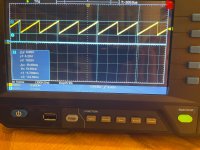
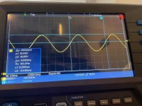
Pic: measurement of S and T with running 33.3 rpm
I measured the frequency on F: 33,3rpm 116hz; 45rpm 146hz; 78rpm 252hz
I'm facing an issue with the speed of my turntable. Initially, the speed began to run away, going faster than 78rpm, and the speed selector stopped functioning altogether.
I've replaced all the capacitors and rectifiers in the power supply and calibrated it using a second (working) SP10. I also replaced C2, C4, C6, and all the capacitors on the logic board, as some of them were leaking. However, this did not resolve the issue.
I later discovered that one of the FG coils had infinite resistance. The defective coil had 510 windings, so I rewound it using 0.1mm enameled copper wire. Since I don't have specialized tools, I used my cordless screwdriver to do this – and it was certainly not an easy task.
In the end, I managed to get 310 windings on the coil before it was full. I measured the resistance on the original, working coil (200 ohms) and the rewound coil (100 ohms). I decided to test it anyway, and although it didn’t fully fix the issue, it improved the situation. The speed selector is now functional, and the speed is more stable, though still not perfect.
I'm not sure how to proceed from here. Should I try using a thinner wire to match the resistance of the original coil, or should I rewind the original coil to ensure both have the same 100-ohm resistance? Or could the problem lie elsewhere?
Thanks for any advice!
Cheers
Jo
Pic: measurement of S and T with running 33.3 rpm
I measured the frequency on F: 33,3rpm 116hz; 45rpm 146hz; 78rpm 252hz
Attachments
Last edited by a moderator:
@Jo.es The FG should use 0.08mm magnet wire and 500 turns. The FG coils are differentially coupled and both wound CCW as viewed from the top of the bobbin.
Before you rewind the FG I would check the output of FG amplifier to see if it's correct for amplitude. If it's correct then perform the tracking adjustments. You may need to go back and forth a few times adjusting each pot to get it into specification.
The number of turns will affect the amplitude and if this is incorrect it could prevent the schmitt trigger from working.
If the output of the FG amplifier is NOT correct then I would rewind the FG.
Last edited:
Thanks a lot warrjon!
I just measured the amplitude on Point F with 33,3rpm. The time seems fine, but the voltage is wrong.
I also measured the
TR 101 E 1,6V (1,8V) B 1,7V (25V)
TR111 E 0,67V (0,6V) B 1,33V (1,3V)
TR112 E 0,17 (0,44V) B 0,83V (1,1V)
In brackets are the values from the service manual. That seems to be off a “little“ bit.
I just phoned a friend and he told me has a basic machine to do the coil winding. I will rewind the coil with the 0,08mm wire.
Will report if this is solving the problem.
Attachments
- Home
- Source & Line
- Analogue Source
- The Incredible Technics SP-10 Thread