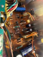
Check transistor TR101 for open and/or short and look for any burnt resistor around the area. If that's ok check TR112.
Thank you so much for your help; I truly appreciate it! I've never had the opportunity to formally study anything in this field, so achieving progress here genuinely makes me happy.
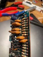
I’ve checked all the TR components—101, 111, and 112—and they are functioning perfectly, along with the remaining TRs on the control board. However, I noticed that all the orange polyester capacitors seem to be leaking slightly. Is this normal? I have some WIMA MKP, MKT, and FKP capacitors available—would these be suitable replacements?
Today, I also rewound the FG coil with 500 turns, which resulted in a resistance of 210 ohms. It’s now working noticeably better than before.
After reassembling everything, I tried adjusting the 50 kHz frequency on T1 via C2, but it fluctuates by approximately ±0.1 kHz. I also attempted to fine-tune the timing with VR101 and VR102, but the timing still varies slightly, by about ±0.2 ms.
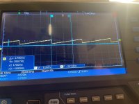
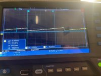
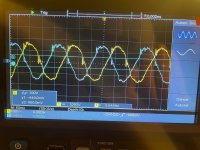
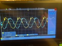
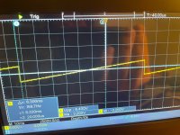
Additionally, I measured the waveforms for A1, A2, and A3 (two seperate screenshots) as well as the frequency F at P10 at 33.3 rpm. Here, the frequency fluctuates between 105.4 Hz and 105.9 Hz.
Overall, the system is running much quieter and better now. However, I’d like to achieve the best possible performance since this will be used in my cutting lathe.
Do you have any suggestions on how to proceed from here?
Thank you so much!
Best
Jo
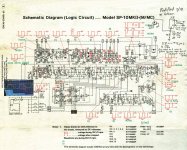
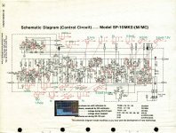
Edit: As I never mentioned it, it's a SP10 MK2
I’ve checked all the TR components—101, 111, and 112—and they are functioning perfectly, along with the remaining TRs on the control board. However, I noticed that all the orange polyester capacitors seem to be leaking slightly. Is this normal? I have some WIMA MKP, MKT, and FKP capacitors available—would these be suitable replacements?
Today, I also rewound the FG coil with 500 turns, which resulted in a resistance of 210 ohms. It’s now working noticeably better than before.
After reassembling everything, I tried adjusting the 50 kHz frequency on T1 via C2, but it fluctuates by approximately ±0.1 kHz. I also attempted to fine-tune the timing with VR101 and VR102, but the timing still varies slightly, by about ±0.2 ms.
Additionally, I measured the waveforms for A1, A2, and A3 (two seperate screenshots) as well as the frequency F at P10 at 33.3 rpm. Here, the frequency fluctuates between 105.4 Hz and 105.9 Hz.
Overall, the system is running much quieter and better now. However, I’d like to achieve the best possible performance since this will be used in my cutting lathe.
Do you have any suggestions on how to proceed from here?
Thank you so much!
Best
Jo
Edit: As I never mentioned it, it's a SP10 MK2
Attachments
Last edited:

The 50kHz is the excitation signal for the variable reluctance resolver to drive the motor, as Dave said it's not critical for speed.
The noise on the zero crossing of the motor drive signal is an issue. The corrosion on that PCB is also of concern. I would fix the PCB if the caps have leaked then replace them. WIMA, MKP will be fine just make sure they are at least 50V. Clean that PCB well and make sure all the corrosion is gone.
If you haven't replace the caps near the drive transistor (C2 C4 & C6) do so. I use either Rubicon 191-8053 or Nichicon 519-4526 (RS part numbers) I prefer the Rubicon if available because they have higher ripple current and longer life.
Also check the 32V and 5V for ripple it should be no more than a few mv AC.
Last edited:
That is very odd that there is 'leakage' by the film caps' leads -- there's nothing inside a film cap to ooze and goo.
Definitely C2 C4 & C6 I use Panasonic FC 100V 12uF part EEUFC2A120 The ones suggested by warrjon are fine too. Buy from a proper authorised dealer, not Amazon or eBay.
The motor coil drive waveform is never going to be great, but whatever you do need to change those 3 capacitors.
I would clean that PCB with a stiff brush and "MG Chemicals 99.9% Isopropyl Alcohol Electronics Cleaner, 475 mL Liquid Spray Bottle"
Then reassemble, sit back and live happily ever after.
Thanks a lot for all your input!
I've already replaced the C2, C4, and C6 capacitors with Panasonic FC series. Today, I'll be replacing the leaking polyester capacitor as well.
I just checked the AC ripple using an oscilloscope. Previously, I had only measured it with a multimeter. This might be where the issue lies. I'm not entirely sure if my budget oscilloscope provides accurate values, but it shows an AC ripple of 28 mVpp at 32.5V and 22 mVpp at 5V. That seems excessively high to me.
In the power supply, I’ve already replaced all electrolytic capacitors with Panasonic FP, Nichicon, and EPCOS components. Additionally, I swapped out diodes D401-406 for UF4007.
Could it really be that the AC ripple is responsible for it still not running stably?
Attachments
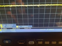
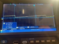
I believe it's not running stably, as the frequency on P10 F fluctuates between 105.4 Hz and 105.9 Hz. If I've read correctly, it should be 105.55 Hz.
Additionally, while performing the period adjustment, I noticed that Wave S is not stable; it appears to be wobbling from left to right.
Additionally, while performing the period adjustment, I noticed that Wave S is not stable; it appears to be wobbling from left to right.
OK got that ! I don't think that is an issue. I think if you put a test record on it might be perfect. Can you see any sign of jitter on the strobe ?
Last edited:
I do have the Ortofon Test Record, but my plinth and tonearm are not properly aligned. My strobe although does not work at the moment. So, I think it makes more sense to stick to using the scope and multimeter for now.
I decided to measure some transistors to check for any potential issues. They all tested fine when using the multimeter's diode check. However, I then tested them while the system was running at 33.3 rpm. I randomly checked a few transistors on the control circuit, and all of them deviated from the values given in the service manual.
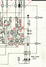
I started with TR118, the "first" transistor on the board, and found it to be completely off. Here's what I measured:
Before the voltages reach this transistor, there is only one resistor and two diodes in the circuit. The resistor measurements are fine. Could it be that the diodes are causing the issue?
I decided to measure some transistors to check for any potential issues. They all tested fine when using the multimeter's diode check. However, I then tested them while the system was running at 33.3 rpm. I randomly checked a few transistors on the control circuit, and all of them deviated from the values given in the service manual.
I started with TR118, the "first" transistor on the board, and found it to be completely off. Here's what I measured:
- During STOP:
- B: 0.12V (should be 0.71V)
- C: 29.6V (should be 31V)
- E: 2.6V (should be 0.41V)
- During START at 33.3 rpm:
- B: 6.66V (should be 0.7V)
- C: 22.9V (should be 20V)
- E: 6.0V (should be 6.1V)
Before the voltages reach this transistor, there is only one resistor and two diodes in the circuit. The resistor measurements are fine. Could it be that the diodes are causing the issue?
Attachments
I believe I am getting closer to identifying the issue after spending half the day taking measurements.
First, I noticed that while 5V are coming out of the power supply, only 4.85V are reaching the logic board, which indicates that there is definitely an issue somewhere in the system.
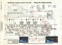
One problem I’ve identified is that the timing at measurement point P10 S should be 19ms, but I’m only measuring 9.5ms. This issue appears at several points in the circuit. Could this problem be related to the area between IC9 and IC10?
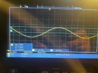
Additionally, I noticed that the sine wave at P1 has an unusual dent at the bottom, which shouldn't be there.
Another issue I found is that the signals at A1/2/3 and P1/2/3 are not stable — both the peak-to-peak voltage and the frequency are constantly fluctuating. I even swapped the motor with a different one, but that didn’t change anything. I’m still unsure about this issue and would appreciate any advice.
I plan to review the entire circuit again to try to understand where these problems could be originating from.
I've attached photos of my measurement results. Hopefully, someone will be able to make more sense of them than I can.
First, I noticed that while 5V are coming out of the power supply, only 4.85V are reaching the logic board, which indicates that there is definitely an issue somewhere in the system.
One problem I’ve identified is that the timing at measurement point P10 S should be 19ms, but I’m only measuring 9.5ms. This issue appears at several points in the circuit. Could this problem be related to the area between IC9 and IC10?
Additionally, I noticed that the sine wave at P1 has an unusual dent at the bottom, which shouldn't be there.
Another issue I found is that the signals at A1/2/3 and P1/2/3 are not stable — both the peak-to-peak voltage and the frequency are constantly fluctuating. I even swapped the motor with a different one, but that didn’t change anything. I’m still unsure about this issue and would appreciate any advice.
I plan to review the entire circuit again to try to understand where these problems could be originating from.
I've attached photos of my measurement results. Hopefully, someone will be able to make more sense of them than I can.
Attachments
The reports on the Kaneta was being shown across the Mk 3 Thread and SP-10 Thread.
The following will bring info back under one thread title.
______________________________________________________________________________________________
Posted on Mk 3
The Kaneta Design SP10 referred to recently went quite well for a debut.
Speed Control proved adequate enough not to be commented on by a SP10 time served EE.
The Tonearm Swap took a extended period to achieve, but once in use nothing was detected amiss as an audible elaluation.
The Kaneta is now housed in Panzerholz,.
I like to think the impression made was quite enlightening, if the merits of adding P'holz were to be immediately made available.
JohnnoG
___________________________________________________________________________________________________
Posted on Mk 3
@ JohnnoG,
I'm not sure what you're saying with respect to the Panzerholz. ???
Don
___________________________________________________________________________________________________
Hi Don
Panzerholz as a material, is in the UK very Difficult to source. It is quite possible the only way to get the P'holz to the UK in the present time, would be to source the Board in Mainland Europe and Pick it Up from a predetermined place if one has a need to Drive into M'land Europe.
I have a small list of suppliers of P'holz that are located approx' 100Km Off Route, for when I undertake a Drive through Germany.
The last Board Bought that was imported and Cut into Plinth Size Boards at a machine shop, prior to sharing between friends.
The P'holz supply owned between myself and a few friends, is very carefully considered for designs it is to be added to. The items that it is added to, do have to make a big impression. The addition of P'holz is classed as the next stage of tidying up the Mechanical Interface, with the benefit of bringing a further audible improvement.
Hence, during the debut of the Variant of the Kaneta Design being used, a decision made was immediate, to where the Kaneta Variant was elevated to being worthy of having the addition of a Panzerholz Plinth.
I have recently seen the Kaneta mounted into the P'holz Plinth with Tonearm in place( PMAT1010 Tonearm, the same as my own Tonearm, which is produced by the other individual who witnessed the Kaneta debut)
The Cartridge Mounted, is the same Brand / Model Cartridge, which is a model I also own. Between both models there is a usage of approx' 150 hours different.
As a task, the work undertaken has been a very speedy turnaround, again another indicator the impression made by the Kaneta debut was very positive.
The Kaneta>P'holz Plinth, is at present at a home of an individual who also has the Mk II mounted on the addition of a P'holz Plinth, that is machined to take the PMAT 1010 Tonearm.
An invite will come soon to offered to visit and be demo'd both versions of the SP10 Mk II side by side.
I will supply my Tonearm/Cartridge to make the A/B comparison a very speedy change over.
Once this is out the way, the Individual who has produced the P'holz Version of the Kaneta Variant, has designed the Plinth to be dual Tonearm Mounting to take a Tonearm up to 12 inches.
This same individual also has their own Tonearm design produced as a Multiple Prototype.
The idea is to have different Signal Wire Types used in a selection of Prototype Models and select the Signal Wire that is most attractive as the end sonic being produced.
When this is out of the way, there is a selection of well respected Branded Tonearms that will be put to use, to enable A/B comparisons between Prototype Model and Branded Arms.
The Kaneta Design was over time of discussion had, rightly or wrongly identified as being the better choice for Tonearm Comparisons
( I have also seen a variety of Posts that are showing Variants of the Kaneta Design for the SP 10 Mk II.
Is it making sense to produce a New Thread to consolidate the info that is being presented? )
JohnnoG,
P'holz is a piece of cake to source in US. I have no idea how expensive it is to ship to UK but should be able to easily find out. Have you tried that? I have gotten fairly large quantities of the stuff a couple times and freight across the US is not outlandish.
Don
P'holz is a piece of cake to source in US. I have no idea how expensive it is to ship to UK but should be able to easily find out. Have you tried that? I have gotten fairly large quantities of the stuff a couple times and freight across the US is not outlandish.
Don
Please elaborate on this 'piece of cake'. I haven't found it to be the case out here in the desert southwest.
Hi Don
Thank You for your suggestion to have a further option to sourcing Panzerholz.
To assist somebody to find a comparative material, I usually refer to a Product Produced as:
Delignified Phenolic Resin Impregnated Wood
Typically the Board is measured at its best when the Structure is 25 Layers of Veneer per Inch Thickness (25mm).
The Layers are also at their best measured performance when orientated as a Cross Grain (Orthogonal / Right Angles) to each other.
An Inch Thick Board is the Typical choice.
I have board in P'holz that is B25 Cross Grain.
I also have Permali Board produced as 3 Inch (75mm) Thickness
A Friend also has a supply of P'holz in 10mm and 32mm (3/8" and 1 1/4") Thicknesses
What is not shared too often is that when P'holz and P'mali were originally selected as a material of interest, to move on from the Massey Plinth Concept.
The Individual supplying the Materials Testing Data / Information, was working with 4" x 4" x 3/8" (100mm x 100mm x 10mm ) Test Samples for measuring the Damping / Dissipation properties.
For many years the individual always stated that when comparing data from same surface area dimensions, but increased thickness samples, the 10mm thickness was not being bettered in relation to the test results.
The same individual always strongly suggested, that even though the measurements for the materials are attractive.
The end sound produced as a result of using the materials and the subjective evaluation of them as a Plinth Material, may not prove to be every individuals preferred experience of a produced end sound.
Thicker Samples, I assume have become attractive, as a result of being more suited structurally, aesthetically ? I am not familiar with a 10mm vs 25mm P'holz Plinth evaluation for noticeable changes to the end sound produced.
I do know of the 25mm vs 32mm P'holz Plinth evaluation where the 32mm was selected for the end sound it was able to produce.
I also know of an individual that had same TT >Tonearm > Cartridge set up in 25mm P'holz Plinths.
One Plinth was secondary Treated with a substance to substantially Increase the Damping of the Plinth Design.
The Secondary Damping Material was able to be reduced in Volume without difficulty and reduced over a period of time, to having no material in use.
The Naked Plinth without any Damping Applied was the Plinth that was always the most attractive and maintained as the design for both Plinths.
My own experiences of Comparisons are where the SP 10 Mk II > Same Tonearm > Same Cartridge > Same Mounting System > Same Audio System. With the Mk II compared side by side in Plinths produced from 25mm Marine Plywood (700Kg per m/3 ) - 25mm MU25 ( 900Kg per m/3) - 25mm P'holz ( 1400Kg per m/3).
The evaluation being, P'holz has produced a presentation and end sound that is very noticeable as a betterment over the other two types of Board Construction.
Brands in the USA that are comparative to P'holz are as follows:
Dymond Wood ( Discovered this one while watching Forged in Fire)
Lignostone ( This Brand also makes Threaded Rod and Nuts in Densified Wood, could be a cool HiFi Rack Material)
Ranprex ( This Brand offers a Tangential Construction, which is the Structure that I believe surpasses Cross Grain when it come to dissipation, as the design for the structure of the board has increased the angles for the Veneer grain between Layers, hence creating increased routes for energy to dissipate).
I would be a very happy soul if able to experience a Tangential Board Construction, I once had an inquiry made to Permali to see if a Bespoke Board could be produced using an increased amount of angles for the Veneers Grain.
Symfonie Wood
Typically today, most who I know that use a P'holz Plinth also have it mounted on a P'holz Sub Plinth.
Out of interest, the Plinth / Sub Plinth separators I have seen used and do use are not the same.
There is room for preference tweaking for the produced end sound by using various separator types.
I will add two other Thermoplastics to make a short list of Materials of Interest and Off Cuts being sought.
Vespel, Celazole, Duratron are now being looked into as materials of interest beyond the usual selection made.
Any spare pieces or knowledge gained through usage, will be appreciated if made known.
Vespel, Celazole, Duratron are now being looked into as materials of interest beyond the usual selection made.
Any spare pieces or knowledge gained through usage, will be appreciated if made known.
- Home
- Source & Line
- Analogue Source
- The Incredible Technics SP-10 Thread