Got some time to work on the Sp10-Mk2a.
Hopefully this video is helpful to determine if it is in lock. Let me know if I should set my scope differently.
Thanks
https://drive.google.com/file/d/1SAfMIF6ZJQBgmZ7vaa49btWhwh8HdBuK/view?usp=sharing
Hopefully this video is helpful to determine if it is in lock. Let me know if I should set my scope differently.
Thanks
https://drive.google.com/file/d/1SAfMIF6ZJQBgmZ7vaa49btWhwh8HdBuK/view?usp=sharing
Sorry, should be ok now.
https://drive.google.com/file/d/1SAfMIF6ZJQBgmZ7vaa49btWhwh8HdBuK/view?usp=sharing
https://drive.google.com/file/d/1SAfMIF6ZJQBgmZ7vaa49btWhwh8HdBuK/view?usp=sharing

After reading more of JP's posts in the mk3 thread, I shot another video of the sync position trace wile stepping through the speeds.
Unless I'm misunderstanding something, I think the offset voltage is set correctly: the trace looks stable and recovers quickly without excess oscillation when changing speed or applying a load to the platter.
Again, thanks for the help and patience.
https://drive.google.com/file/d/1GqJKdTVeaofOqBrtWgkLy23YF2JxZ_jh/view?usp=sharing
When I mentioned a vibration, I may be over critical. I'm comparing it to my VPI TNT Jr. where the motor is in a seperate massive chassis and connects to the massive platter via a belt. If you touch the plinth on it, you feel nothing. If I touch the motor pod on the VPI, you do feel a vibration, similar to the SP-10. Maybe I just need a 100 lb cast iron plinth.😀Seems fine. If it starts vibrating after being warmed up, back it off a hair - a little overshoot is fine. Is your vibration gone now? Other cals able to be set?
All other cals are fine except RS current setting which I can't get below 0.162 V.
Checking w&f with the Feickert Adjust+ software & test record, I get .08% while my Denon which is closed loop gets .03%. I've attached plots of each if anyone is interested. Strangely, they're both a 33.41, possibly a software glitch.
Thanks
Something’s wrong - shouldn’t feel a hint of vibration. How much is the FG signal moving around?
FG, frequency generator, or what the service manual calls "liquid crystal oscillation"? That's rock solid when viewing with my scope - see attached of wave form. Could this be mechanical? I do have a new thrust pad that I haven't installed yet.Something’s wrong - shouldn’t feel a hint of vibration. How much is the FG signal moving around?
Attachments
FG is the frequency generator from the motor. Control board CN205 (FG Out). Mess with the platter while watching it so you get a sense of it.
The manual shows FG signal in, IC201 pin 16? When I attach my scope to that I see a clean sine wave but it's amplitude undulates (grows and shrinks) at what looks like a constant frequency. It's more noitcable at 45 & 78. The vibration I feel seems to pulse at that same frequency but the frequency of the vibration doesn't change.FG is the frequency generator from the motor. Control board CN205 (FG Out). Mess with the platter while watching it so you get a sense of it.
Sorry if I'm missing something.
Thanks
I've also looked at the Amplifier output AO & speed output VO signals on IC201 but they're pretty chaotic or I don't know how to set my scope properly.
Connector 2, pin 5 🙄 - just give me enough time...
The magnitude of the sine wave pulses more dramatically than FG in that I saw on IC201. I'll shoot a little video.
The magnitude of the sine wave pulses more dramatically than FG in that I saw on IC201. I'll shoot a little video.
Here's the pulsing sine wave on CN2 pin 5.
https://drive.google.com/file/d/14UqbRU7M7xZ3ltJakmwQA_5dd0IAoHje/view?usp=sharing
https://drive.google.com/file/d/14UqbRU7M7xZ3ltJakmwQA_5dd0IAoHje/view?usp=sharing
Well, my own MK3 is now loosing lock after many years too ! When yours is vibrating what does the strobe look like ?
The vibration is very subtle. I thought it was normal and I was being a neurotic audiophile. When looking at the strobe, I think I see the markers oscilating back & forth ever so slightly.When yours is vibrating what does the strobe look like ?
Regarding the FG out signal. Does this bouncy behavior tell us something? I'm not in lock? Offset voltage is wrong? Something else?
I scoped CN2 7 and it looks the same as what I saw on CN2 5 - a pulsating sine wave.Sorry was thinking MK3. CN2 5 is ST2, which isn't what your video shows. FG out is CN2 7.
What does the motor drive look like? Scope the collector of one of the drive outputs Q140, Q142, Q144.
I scoped the collectors on those transistors and they had this somewhat chaotic behavior:
https://drive.google.com/file/d/1VVY0ZJZdFGUXEnQ9pLhxsZWkAFvwkALT/view?usp=sharing
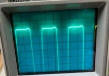
Ah, my ignorance is showing. Is it easier to view low frequency signals with a digital scope? This is the best I could get with my Tektronix 2235 unless I'm missing something. My multimeter displayed 5.6 Hz and other values as it tried to figure it out but 5.6 kept re-appearing.What’s your time base? You’re looking for a 5.55Hz signal
Scope was set at 50 ms/div. The signal appears somewhere arount 5 Hz.
https://drive.google.com/file/d/1oU16sx2hqfKqV17ne6GAMlDj3q_538Yn/view?usp=sharing
I have never thought about that. I have only used Tektronix and Keysight digital scopes for well over 30 years now.
- Home
- Source & Line
- Analogue Source
- The Incredible Technics SP-10 Thread