It could be a bad pot but turning the pot changes the voltage measurement consistently until I approach the goal of 0 V at which point it jumps back up to > 1 V & I can hear the motor starting to make funky sounds.
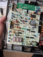
For the record, I haven't done a dogmatic recap of every electrolytic. The sticker on the motor says 1983 & it appears that some caps have been replaced because they look different from the others and it looks like someone marked them with blue nail polish perhaps to flag them? I have no idea but you can look at the attached pic.
Thanks for all the help!
Attachments
Info in the MK3 thread will be relevant to the MK2A. Nothing of the MKII electronics aside from the PSU is.
I typically advise people to not touch offset voltage - unless the VR is bad, it doesn't move unless you change components in that circuit. Easiest way to set it is empirically: #62
You're basically adjusting the current feedback to the motor drive IC. Too low and the drive won't provide enough current to react to changes, and too high and the motor will fight itself. Basically under, over, and critically damped. The latter is your goal. Not really what's going on, but puts it in terms most folks can understand.
Thanks JP I hadn't thought of that.
#62 is here https://www.diyaudio.com/community/...technics-sp-10-mk3-thread.275613/post-4367671
It looks like I set both mine empirically too and 9 (nine) years later both are still perfect in that respect, only the LED sockets on one went intermittent.
It looks like in #64 I went too far and destroyed the output transistors.
That thread shows our frustration but it apears that JP's and mine are all working fine !
I was able to set the offset voltage and VR101 had noticable impact. When too far off the platter would start spinning pretty fast. When it was at 30 mV the platter stops, or tries to. I've attached a link to a video showing it at 30mV - the video is about 30MB, too big to attach.
I got the RS setting down to 0.162V and everything seems to be working fine. I do feel the slightest vibration when running but it's about the same as I feel from my Denon DP-80 - something normal from DD turntables? Would it be advisable to replace VR201 or start re-capping?
Here's the video if anyone wants to see it
https://drive.google.com/file/d/1ZITjOT4hjjiHjKA-wV53IBPNbfI86umM/view?usp=sharing
Thanks
No. Should be trivial to get RS current down to a few mV.I do feel the slightest vibration when running but it's about the same as I feel from my Denon DP-80 - something normal from DD turntables?
Last edited:
Meaning that the brakes are on?None of the video looks right, is it in lock ?
I followed the procedure:
Removed Test CN3 and applied 40mV between pins 5 & 3
Turned on TT power supply and hit start (33 rpm)
Adjusted VR101 to get 30mV across Test CN1
At 30mV the platter stops, or tries to. Turning VR101 beyond the 30mV point causes platter rotation to reverse.
Thanks again for the help and patience
Sorry, my ignorance is showing. How do I check that? I have a scope & multimeters.No, the triangular waveform with the notch, is in lock (PLL) ?
If the strobe is still and very slight pressure on the platter just moves the strobe but still essentially still, then it is locked.
I suspect it isn't locked ?
I can't find the reference to the saw-tooth waveform and I don't think I have a MK2A service manual only the MK3 which as we all know is similar. JP can probably step in here ?
I suspect it isn't locked ?
I can't find the reference to the saw-tooth waveform and I don't think I have a MK2A service manual only the MK3 which as we all know is similar. JP can probably step in here ?
The adjustment runs it open loop and it’s barely spinning anyway in the video. For normal operation if the ST2 waveform is stable, it’s locked.

Here's a video - I think it's locked? I pressed farily hard on it.If the strobe is still and very slight pressure on the platter just moves the strobe but still essentially still, then it is locked.
I suspect it isn't locked ?
I can't find the reference to the saw-tooth waveform and I don't think I have a MK2A service manual only the MK3 which as we all know is similar. JP can probably step in here ?
https://drive.google.com/file/d/1bCGBTRCALzUST28P8R_uvJJcA9EJRVBs/view?usp=sharing
So we've concluded that it is in lock based upon the other video?None of the video looks right, is it in lock ?
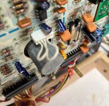
The first video of the platter almost stopped was shot while performing the offset voltage setting procedure which required removing the Test CN3 plug that jumps 1-2 and 3-4 under normal operation (see photo). You then inject 40mV between 3-5 but so it's not like normal operation where the platter would spin. It seems very odd that concidentally when I got close to the target output of 30mV, the platter comes to a stop, or tries to. You can see in the video that the platter does stop & reverse then reverse again while hovering around being stopped.
I've attached a copy of the service manual for reference.
Again, thanks for all the help.
Attachments
Hi JohnEPA-A501H - 8g
EPA-A501M - 10g
EPA-A501L - 18g
EPA-A501E - 6g
EPA-A501G - 14g
EPA-A250 - 14g
EPA-A505 - 6g
Are these arm mass figures ? Do you have the document they came from please ?
Thanks Dave
- Home
- Source & Line
- Analogue Source
- The Incredible Technics SP-10 Thread