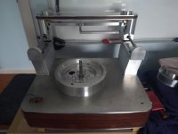
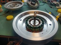
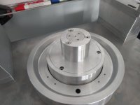
Thank you for the kind explanation. I understand better, and the mcu controller is a good news.
I asked because for Victor brand/Micro Seiki I found out several different boards and different motors could work out together, albeit they were more or less some TT-71 motors (various outside number but quite same internal).
I asked because for Victor brand/Micro Seiki I found out several different boards and different motors could work out together, albeit they were more or less some TT-71 motors (various outside number but quite same internal).
12 poles is most common so there is some compatibility for some decks but FG generation frequency and level could be way different for different motors for a start, or some could use TT rim sensors even, then there is the impedance of the stator coils etc and the effect of that on the driver bridges. Are they designed to give say 40V @ 100mA or 10V @ 400mA per phase for a specific motor? It's not a much a "diy bodge will work" thing really....
Thank you as well, I see I have yet much to learn. It's just I felt that it is sad to see all this technology and craftsmanship skills go to waste. That's why I stick with belt drives for now despite my admiration for this model and the TT-101.
My apologies for my immature previous question.
My apologies for my immature previous question.
Was there a post somewhere on modifying the obsidian cover hinge with a bigger screw ? Can't find it ? Thanks DaveBlock
I'm guessing you're talking about the the bolt that adjusts the hinge spring tension. These hinges were bent and needed straightening before being drilled and tapped for larger bolts. IIRC these are M6 bolts.

Do you have the post number please ? I somehow thought it revolved around a M5 rivnut ? I'm considering putting a spacer inside as the spring cap has an indentation ?
Many thanks Dave
Many thanks Dave
If you tap for a larger size it’s just going to pull out again at some point. Using a threaded insert is a much better fix.
https://www.vinylengine.com/turntable_forum/viewtopic.php?p=1315324#p1315324
https://www.vinylengine.com/turntable_forum/viewtopic.php?p=1315324#p1315324
That's it ! Thank you. I don't monitor Vinyl Engine since I got banned for being a smart-a*se years ago.
BTW that insert with the "shoulder" is good, who makes it ?
BTW that insert with the "shoulder" is good, who makes it ?
Last edited:
It's called a "press fit insert" and available from Mcmaster-Carr (mcmaster.com) among other places.
Ah ! Fount it under "press fit nut" and or "clinch nut"now that I know what it is I can easily get one here in the UK. Thanks
The insert is not a bad idea although if I did this again I would use a 3mm steel plate with M5 thread to spread the load on the aluminium hinge preventing it bending again.
I was pondering that too. As I have them on the bench but not yet disassembled , does anyone have a photo of the pressure-pad/cup that is on the spring ?
Thanks. As hinted in an earlier post I wasn't sure if it took an external drive waveform or self commutated as you describe. So it should be possible to spin up the motor at some random speed even with malfunctioning logic or control boards by giving it a suitable current limited input voltage from a bench PSU? FWIW all the waveforms on the control board look about right as far as one can tell from spinning it by hand so probably not the drive board but if I can rule it out by say feeding it 10V DC via a 10K resistor and see it spin up to say 110RPM then that would be great.
I guess this is one of those repairs where you end up spending 30 hours on it and can only charge for a fraction of that but it is years since anything beat me🙄
Sorry, missed this while on the road. Really easy - pull the logic and control boards out, and with your bench PSU referenced to the SP-10 backplane 0V line, give it around 24.5VDC and it'll start to spin. The lower the voltage the more drive current, but no need to go more than 1V lower, and watch the motor speed - you're playing with mV to reach equilibrium. You may need to push start it, or give it a negative "goose".
Thanks. For now it's decided to run again.... nothing like the "fun" of an intermittent fault eh!?Sorry, missed this while on the road. Really easy - pull the logic and control boards out, and with your bench PSU referenced to the SP-10 backplane 0V line, give it around 24.5VDC and it'll start to spin. The lower the voltage the more drive current, but no need to go more than 1V lower, and watch the motor speed - you're playing with mV to reach equilibrium. You may need to push start it, or give it a negative "goose".
Ah,i know the guy you talk of, phil, hes just bought my mint condition sp10 mk2 as a stop gap while you repair his one. Small world isn't it.I was intrigued by the use this SP10 is being put to by the customer. He uses it as a cutting lathe to cut records one at a time with a cutting head on a linear tracking "arm"! I didn't know this was "a thing" even!
Aha yep. And we "know" each other from pfm and Audioflat.Ah,i know the guy you talk of, phil, hes just bought my mint condition sp10 mk2 as a stop gap while you repair his one. Small world isn't it.
I ended up going for a full re-cap and underneath a 100uf 16V electrolytic on the logic board there was a leak which, whilst not visible from above while capacitor in place, had corroded through the PCB track severing it on both sides of the capacitors lead out wire.
Thanks for the help guys 🙂
Thanks for the help guys 🙂
- Home
- Source & Line
- Analogue Source
- The Incredible Technics SP-10 Thread


