It was just a comment on veneering in general. Trickiest thing I did with epoxy and veneer were aluminum panels which of course involved acid etching, etc. I used West Systems 105 epoxy with 205 hardener as I was also finishing the wood in scraped and 0000 steel wool polished epoxy. It was a decade ago, but IIRC ensuring no movement through the initial set and cure was of great importance, so the parts were baged for 24 hours.
I use a honed veneer saw for straight edges afterward, and rough cut with sanding for radiuses. Other methods led to too much chip-out for me, but in all likelihood this was all due to my lack of experience. I just don't veneer often.
web page


I use a honed veneer saw for straight edges afterward, and rough cut with sanding for radiuses. Other methods led to too much chip-out for me, but in all likelihood this was all due to my lack of experience. I just don't veneer often.
web page
Thanks JP. Said 106 and 107 bot I really meant 206,207. Congrats on getting it all done with 205. I think I'm too slow for that pot life. Of course, if I did it in the snow and then brought it in side to cure it would probably work.
Oops. Bad manners on my part. Your equipment looks awesome. I'm sure it sounds at least as good. Congratulations.
Hi Don,
I've been a little sidetracked with my linear tonearm and setting up a new collet chuck on the lathe to improve concentricity in small machined parts.
I think I have a solution to the runout problem and the new collet chuck will be part of the solution in reducing runout in the machined parts. Having had the inverted bearing with only the 2 point contact sitting on the bench for a while I've discovered that I'm going to have to add a second sleeve to the top near the ball/thrust pad because the rotor can tilt. If the platter is pushed the ball pops out of the cup.
Because there is very little clearance inside the motor between the stator and rotating parts this could cause a catastrophic motor failure if the platter tilts. So I'm going to have to go to a 2 sleeve bearing with ball running on a flat thrust pad. This should still be good as the Vesconite after a few hours running becomes quieter and is almost inaudible with a stethoscope on the bearing housing.
@warrjon and all,
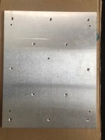
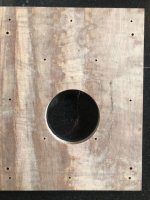
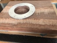
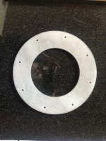
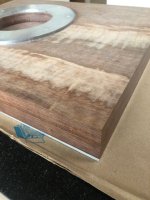
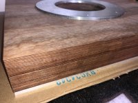
Attached are parts to my build under construction. This is basically a plagiarized version of warrjon's latest Permali build. It is 1/4in Al on the bottom, 25mm Panzerholz B25 400mm x 500mm 2 pieces and a 1/4in Al ring for the motor flange to mount on. The Al bottom plate and the 2 Pz pieces were clamped in exact position then pined together with removable pins and drilled to the appropriate depth. the Pz pieces will then be glued together and bolted together for a "press" fit. I had 2 options: machine screw them or vacuum bag them. Next time I may vacuum bag them as the pins held them very precisely. There are 12 6M Machine screws holding them together just for the Epoxy glueing.
The tricky parts of the build are:
1. To hold the 2 Pz pieces in exact position because they have been CNC milled at exactly 400mm x 500mm. The pins worked perfectly.
2. Mount the motor with an exact co-linear axis through both Pz pieces perpendicular to the mounting plate. This is necessitated by my own requirement to both mount the motor to the top Pz piece and "tie" the spindle shaft housing cap to the bottom piece without putting pressure on the spindle housing on the lower piece. I didn't want to potentially move a bearing off axis.
3. Drill and tap a bunch of blind holes through the bottom pieces and threaded in the top piece. My experience tells me the 2 pieces won't tighten against each other if they are both threaded. So, I drilled a 5mm hole through the Al and Bottom Pz piece terminating in a blind hole in the top piece. I then tapped the top piece and re drilled the Bottom and Al pieces for the 6mm bolt. All bolts in this build are 316 stainless. Thanks Bon.
4. Building a spacer so the Tonearm headshell underside is exactly parallel to the record surface. I will 3D print a mockup spacer to verify the geometry and then machine an aluminum pice to a verified spec.
5. Wiring the electronics to the motor. Tedious but should be perfect with continuity checks.
This is DIY but certain aspects have to be very precise. Once I know what I'm doing I could have it CNC'd
That's what I am trying to do and why I am doing it. Suggestions are welcome.
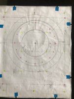
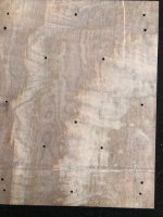
The pics are the individual pieces and the pieces stacked. The white paper is a bolt pattern I made to make sure I didn't have any bolt positioning problems.
Don
Attached are parts to my build under construction. This is basically a plagiarized version of warrjon's latest Permali build. It is 1/4in Al on the bottom, 25mm Panzerholz B25 400mm x 500mm 2 pieces and a 1/4in Al ring for the motor flange to mount on. The Al bottom plate and the 2 Pz pieces were clamped in exact position then pined together with removable pins and drilled to the appropriate depth. the Pz pieces will then be glued together and bolted together for a "press" fit. I had 2 options: machine screw them or vacuum bag them. Next time I may vacuum bag them as the pins held them very precisely. There are 12 6M Machine screws holding them together just for the Epoxy glueing.
The tricky parts of the build are:
1. To hold the 2 Pz pieces in exact position because they have been CNC milled at exactly 400mm x 500mm. The pins worked perfectly.
2. Mount the motor with an exact co-linear axis through both Pz pieces perpendicular to the mounting plate. This is necessitated by my own requirement to both mount the motor to the top Pz piece and "tie" the spindle shaft housing cap to the bottom piece without putting pressure on the spindle housing on the lower piece. I didn't want to potentially move a bearing off axis.
3. Drill and tap a bunch of blind holes through the bottom pieces and threaded in the top piece. My experience tells me the 2 pieces won't tighten against each other if they are both threaded. So, I drilled a 5mm hole through the Al and Bottom Pz piece terminating in a blind hole in the top piece. I then tapped the top piece and re drilled the Bottom and Al pieces for the 6mm bolt. All bolts in this build are 316 stainless. Thanks Bon.
4. Building a spacer so the Tonearm headshell underside is exactly parallel to the record surface. I will 3D print a mockup spacer to verify the geometry and then machine an aluminum pice to a verified spec.
5. Wiring the electronics to the motor. Tedious but should be perfect with continuity checks.
This is DIY but certain aspects have to be very precise. Once I know what I'm doing I could have it CNC'd
That's what I am trying to do and why I am doing it. Suggestions are welcome.
The pics are the individual pieces and the pieces stacked. The white paper is a bolt pattern I made to make sure I didn't have any bolt positioning problems.
Don
Attachments

@donhughes111
5. The OEM motor connector has numbered pins. Just transfer 1 wire at a time to a circular 12 pin maintaining the same pin number to each wire.
Don't remove all wires from the connector because there are a multiple same coloured wires that are NOT interchangeable.
5. The OEM motor connector has numbered pins. Just transfer 1 wire at a time to a circular 12 pin maintaining the same pin number to each wire.
Don't remove all wires from the connector because there are a multiple same coloured wires that are NOT interchangeable.
.
Did you also build your cantilevered arm boards? I’d like to start thinking out/designing a plinth as well, but I’m getting hung up on little things like what tonearm I’d want to use if I’m investing a bunch of time and effort into a project like this. If I can get past some speed bumps like arm boards I think it would help.1. I was originally against cantilevered arm boards as I thought they would ring. But after building my current plinth and measuring acoustic feedback at the arm mount on the armboard I have changed my mind. The other advantage is any tonearm can be mounted. Just make sure you have enough clearance between the bottom of the arm and top of plinth to install the cable
In reference to my previous post, something like this arm board from acoustand Spare arm board- alloy definitely seems interesting for those of us that can diy woodwork better than metal, haha.
.
Did you also build your cantilevered arm boards? I’d like to start thinking out/designing a plinth as well, but I’m getting hung up on little things like what tonearm I’d want to use if I’m investing a bunch of time and effort into a project like this. If I can get past some speed bumps like arm boards I think it would help.
Yes I made the arm boards from 1/2" 6060 T5 aluminium.
They could be made from Pz or plywood and could be square like the JC Verdier. It would be easy to make them like this with woodworking tools.
The beauty of this type of arm mount arrangement is the height of the riser and length of the armboard can be varied so any tonearm 9-12" can be installed on the TT so long as there is sufficient clearance under the TA to install the cable.
I tried to keep the armboards short but I don't have enough clearance under the short armboard to install the connector in the Technics EPA-100, so it needs a long armboard.
The round cutouts in the top aluminium plate are not needed.
Not sure if I've posted these pics so here they are (again maybe) for others reference in what I did. The motor pod is 25mm tall and 220mm OD.
The bearing housing is the only part of the motor that goes down into the Permalli.


The bearing housing is the only part of the motor that goes down into the Permalli.
Warren, is the top aluminum plate Epoxy'd to the Pz. How did you squish them together. I don't see any fasteners.Yes I made the arm boards from 1/2" 6060 T5 aluminium.
They could be made from Pz or plywood and could be square like the JC Verdier. It would be easy to make them like this with woodworking tools.
The beauty of this type of arm mount arrangement is the height of the riser and length of the armboard can be varied so any tonearm 9-12" can be installed on the TT so long as there is sufficient clearance under the TA to install the cable.
I tried to keep the armboards short but I don't have enough clearance under the short armboard to install the connector in the Technics EPA-100, so it needs a long armboard.
The round cutouts in the top aluminium plate are not needed.
Have there been any other areas where you’ve noted corrosion from mounting in a resin containing plinth, perhaps less easily replaceable objects such as the motor assembly, or is everything else just fine?@donhughes111
For peace of mind I use 304 stainless fastenings where possible. I found hardened steel bolts through resin/bento corroded over time.
I concluded the resin outgassing is corrosive. Since densified wood products like Panzerholz, Permali etc are resin infused, they may also be corrosive to hardened steel, although I have not seen such reported. Where the resin/bento is sealed with many coats of primer/paint/clearcoat I have seen nothing of concern. It is only the through holes into the raw material where I notice the problem. Nothing to report since using 304 stainless bolts/nuts/screws.
Here are 5 mkII bolts after about 5 years in a resin/bento plinth. The end threads and hex caps outside of the resin/bento are unaffected. The replacement 304 stainless hardware are still perfect.
Warren, is the top aluminum plate Epoxy'd to the Pz. How did you squish them together. I don't see any fasteners.
The top and bottom plates are glued to the Permalli with West System epoxy. No fasteners in the plinth apart from the pods.
To glue up the plinth I used 4 bits of 4x2 across the plinth to ensure good bonding in the middle as I don't have deep clamps. Then just a fer clamps around the edge.
If you look closely at the photos in post #2334 you will see that the bolts heads, which are outside the plinth underneath, and the screw threads which are into the top chassis, are corrosion free. It is only the bolt shaft and exposed threads that show corrosion. As I mentioned, stainless fasteners show nothing worthy of mention. The bento/resin plinth is sealed internally with with primer, undercoat and topcoat and I have no evidence of corrosion other than the exposed bolts. This is after about 8 years use.Have there been any other areas where you’ve noted corrosion from mounting in a resin containing plinth, perhaps less easily replaceable objects such as the motor assembly, or is everything else just fine?
By comparison, I have seen mkII chassis and platters badly corroded by damp conditions or liquid spills. I have in my collection an OEM platter with the strobe markings partially eaten away by corrosion.
- Home
- Source & Line
- Analogue Source
- The Incredible Technics SP-10 Thread