The circuit being universal - used in the MK2A, MK3, 1300/1400/1500/150 MK2, my take is if you're going to step on the gas, you should know how hard you're stepping. Only the MK2A and MK3 have this adjustment.
I put Q260 back on the board. It was causing issues with start/stop and brake. Sometimes the electronic brake wouldn't fire, sometimes it'd surge, sometimes it'd spin the platter faster, sometimes it wouldn't start. It's burning in now.
I put Q260 back on the board. It was causing issues with start/stop and brake. Sometimes the electronic brake wouldn't fire, sometimes it'd surge, sometimes it'd spin the platter faster, sometimes it wouldn't start. It's burning in now.
I've been through a few rounds with VR101 since my last update.
The net of it is the adjustment is beyond sensitive, to the point where it appears even possible board flex may alter it. I've had it set with the control unit open and the front panel off (you have to in order to reach the header to inject 40mV) only for problems to resurface later. This last round just attaching the front panel caused the occasional motor vibration.
I've gone back to setting it empirically. I zoom in on the notch in the ST2 waveform, retard the platter with my finger, and check the overshoot of sync position when I release the drag. My first attempt I set it to the point where I could no longer detect any over shoot, and put the cover on.
After 4-5 hours it started acting up again, so I slipped the cover off just enough to access the VR and backed it off a little bit more. After that it ran another 4-5 hours without issue, and I'll let it run all day today as well. I'm going to replace VR101 with a ten-turn. I noticed pushing on the body of the pot will change the setting.
Last edited:

.
Hmmmmmmmmm it will turn and lock now, but only if you give it a push start. However the PLL is all over the place and as John said it varies with VR101 as well. I'm going to make up a connector to fit CN206 to make sure my scope probe does not slip.
I am as you know running the +/- 32V from bench PSU's, as you turn VR101 clock wise the current rises alarmingly from about 80mA (good old fashioned moving coil meters on the PSU) to up to my current limit of 800mA. I blew the output transistors when I turned it fully clockwise with the existing (rebuilt) power supply, did the fuses blow? no they didn't..........
I have other work to do, but I'm confident that I'll be back in a few days with it like it was when I bought it.................... But with way more knowledge
.
Nice chips! 🙂
Since yours is apart, would you mind measuring the foot print for VR101? I'm going to get a better ten-turn.
Mine ran ~15 hours yesterday without issue.
Since yours is apart, would you mind measuring the foot print for VR101? I'm going to get a better ten-turn.
Mine ran ~15 hours yesterday without issue.
The two outer pins are 0.2" apart, the middle pin is in the middle spaced out by 0.1" from the centre line of the two, the adjustment needs to be 2 pin side. It's 2K.
This might be difficult, if you find one can you give me the manufacturers or digikey/mouser part number please ?
This might be difficult, if you find one can you give me the manufacturers or digikey/mouser part number please ?
Well, it's going but sometimes needs a push start. The waveforms on the three driver outputs are very rough indeed, not like a working MKII so I'm looking at this.
If the motor isn't being driven properly, this could account for something ?
If the motor isn't being driven properly, this could account for something ?
Result, but at a price
.
Mmmmmmmmm no output from P3 at all. 🙁
Changed to a new motor, as you do, and it's perfect, and not remotely critical. 🙄
Also the motor waveform is ragged, but mostly OK 🙂
.
.
Mmmmmmmmm no output from P3 at all. 🙁
Changed to a new motor, as you do, and it's perfect, and not remotely critical. 🙄
Also the motor waveform is ragged, but mostly OK 🙂
.
Last edited:
Can you post a scope shot of the motor waveform? I'll do the same next time I'm in to mine.
Looks like the 3339S will work http://www.bourns.com/data/global/pdfs/3339.pdf.
Looks like the 3339S will work http://www.bourns.com/data/global/pdfs/3339.pdf.
- The pot needs to be side adjust and preferably 10 turn, M64P202KB40 ?? see below ?
- I'll do a screen shot later
- Have you looked at all three phases ?
- I am now sure the manual is not correct, I get perfect lock without it being critical at all, but only when the 33rpm is set to 6ms not 8.5ms, and this is where it was set in the first place (after getting all three phase inputs and outputs correct)

Last edited:

OK, here is the drive from the collectors of the output transistors, all three are similar. Click on the image to get it bigger.
Mine was a bit nicer looking than that - close to what I recall my MKII looking like.
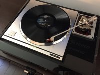
Here's my mock-up for now. The broken plinth is courtesy of from japan.co.jp, who think one layer of bubble-wrap should be fine. However, they did package the table exceptionally.
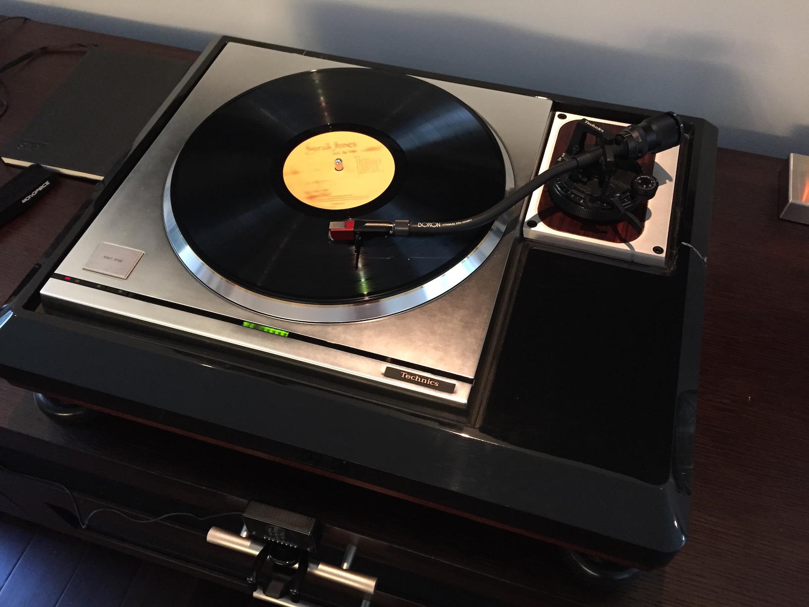
Here's my mock-up for now. The broken plinth is courtesy of from japan.co.jp, who think one layer of bubble-wrap should be fine. However, they did package the table exceptionally.
Attachments

The pot needs to be side adjust and preferably 10 turn, M64P202KB40 ?? see below ?
Most of the pots I can find the leg position puts the adjustment on the opposite side we need it to be. The 3339S is the only multi-turn I've found so far.
Have you looked at all three phases ?
Yes
I am now sure the manual is not correct, I get perfect lock without it being critical at all, but only when the 33rpm is set to 6ms not 8.5ms, and this is where it was set in the first place (after getting all three phase inputs and outputs correct)
Which bit isn't critical with 33 at 6ms? VR101?
Which bit isn't critical with 33 at 6ms? VR101?
Yes, VR101 is now not critical at all.
OK, clearly I have moved VR101 as I'm now getting 7.4mS 7.0 and 4.3, much closed to that specified. But as I said, not at all critical including the setting of VR101
VR101 seems to be the feedback gain control, that has side effects in that it affects the PLL timimg. To far anticlockwise and the turntable won't start and/or achieve speed. To far clockwise and it hunts/overshoots. So philosophy is to turn it up too high, check in lock, back it off, then re-adjust the PLL timing. This seems to work every time. My issue with the unstable nature was a faulty motor with only 2 of the 3 outputs working.
However the driver waveform that I published recently is worrying.
The drive waveform is shown on the service manual on AN1-3 and it's anything but sinusoidal, and matches what I get. How this can be converted to a perfect sinewave as shown on the collectors of all the drivers is a complete mystery. John, when you get a chance could you send me a screen shot of the collector of any Q101-6 please ?
Absolutely. Hopefully this weekend, or it'll have to wait a week as I'll be out of town.
If you drag your finger enough to retard the strobe and let go, does ST2 overshoot sync position and fall back? That was what I saw with the VR101 adjustment if it was set low. There was a very small window between no overshoot and the motor fighting itself. Right now I've the slightest overshoot when cold otherwise it's fight itself when hot.
If you drag your finger enough to retard the strobe and let go, does ST2 overshoot sync position and fall back? That was what I saw with the VR101 adjustment if it was set low. There was a very small window between no overshoot and the motor fighting itself. Right now I've the slightest overshoot when cold otherwise it's fight itself when hot.
Good question, as I went out to the workshop I pondered on underdamped, critically damped and over damped, postulating to myself the first two or half way would be the best ?
However with a light finger test, and the strobe slightly retarded, the time period went longer and the current went up, on releasing my finger, straight back, no overshoot and critically damped. With a lot of finger pressure where the current was about 600mA there was overshoot. So for maybe 100X normal loads it's critically damped, and that is very, very good !
However with a light finger test, and the strobe slightly retarded, the time period went longer and the current went up, on releasing my finger, straight back, no overshoot and critically damped. With a lot of finger pressure where the current was about 600mA there was overshoot. So for maybe 100X normal loads it's critically damped, and that is very, very good !
It'll be interesting to see what happens when you put the cover on and let it get to full operating temp in the control chassis - that's where it bit me. My VR101 seems to be touchier than yours though - if I feel it move when I adjust it I know I'm miles too far. I'll order a replacement so I can put it in when I get back in town.
I'm not running +/- 32V from a bench supply, but I had a meter across 32V and VCS to watch the current to the motor.
Unfortunately I didn't save any scope shots, but thinking about your drive waveforms I believe I had ones similar to you when I had VR101 set low. I'd set sync positions per the manual and get VR101 dialed-up (iterative) to where it just stops overshooting and take look at the drive waveforms again. I *think* that's when mine cleaned up.
I don't think this warrants its own thread, so I'm going to put it here as tangential to the MK3 project.
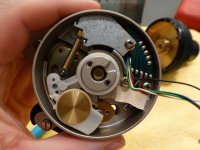
I stumbled across an EPA-A500 series wand I thought I'd never find, so I've been dying to give it a try. However, the anti-skate dial on my B500 base wouldn't budge, so I cracked it open last night. I wasn't able to find any information or pictures in regards to working on one of these, so perhaps this will be useful to someone down the road.
The nameplate at the base of the pillar needs removed to get in to the arm. I used a hair dryer to heat it up to soften the adhesive. Using a razor blade I was able to slowly work my way under the plate and lift it. This was an iterative process of heating and prying. You want to be careful to not scratch the paint, or bend the plate.

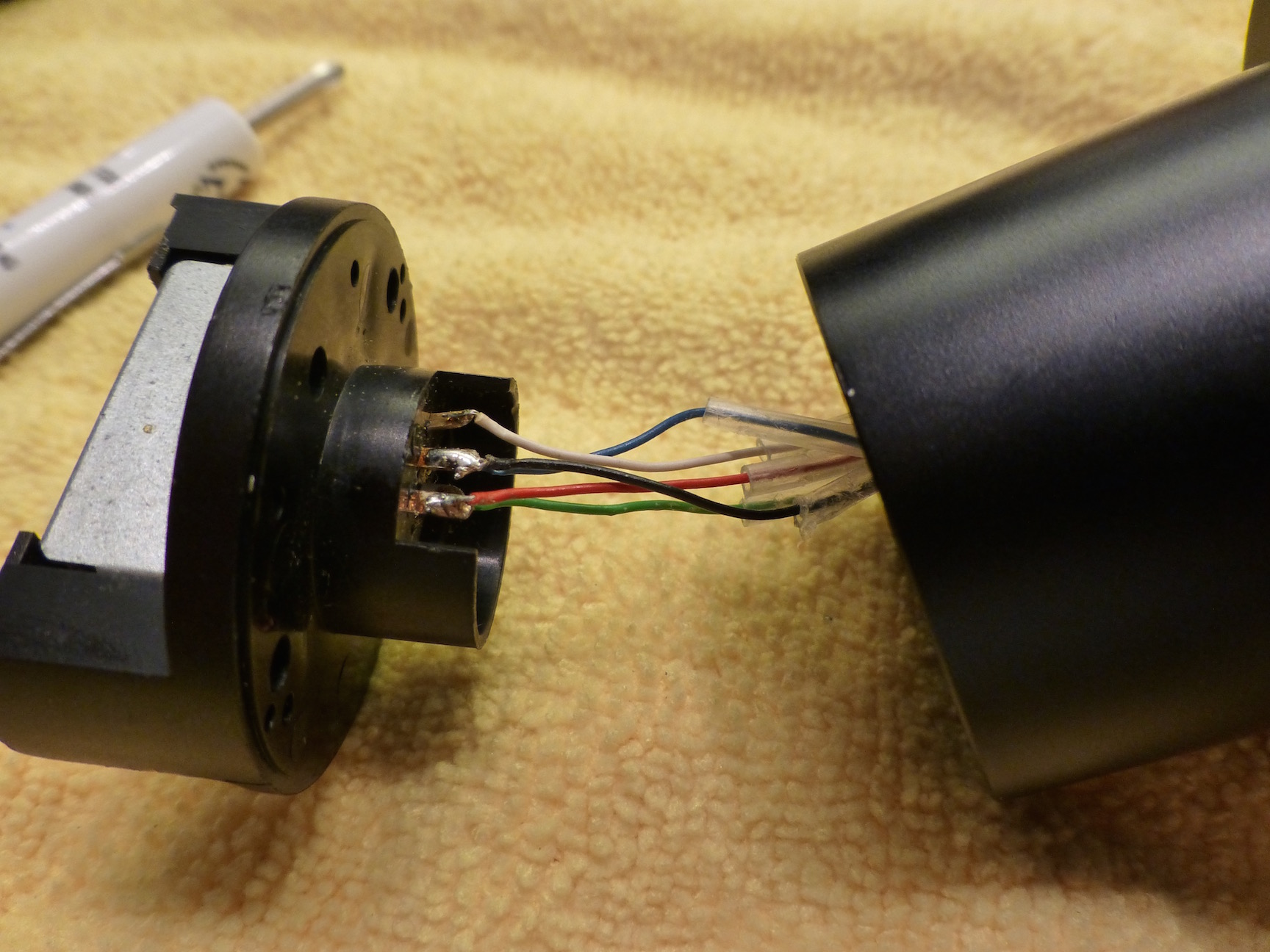
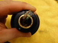
Remove the two larger screws and wiggle the connection block out of the pillar. You'll need to desolder the wires from the connection block.
There are two screws in the pillar that hold the pillar to the base of the arm. These have very strong thread-lock on them, so it's very important to make sure you've the correct size driver and are able to apply enough pressure to break them loose. It's quite difficult to find a good way to hold the base and do this without applying pressure to the bearings.
The two screws by the lift handle hold it in place, and three screws (one is under the spring) hold the zinc colored plate down which is the entire lift mechanism. You also need to remove the little rubber block (it's glued in, so be careful) that the wires go under, and the lift arm from the top in order to remove the lift mechanism. The lubricant-turned-glue on my arm was only at the anti-skate dial itself, so it wasn't necessary to do this.
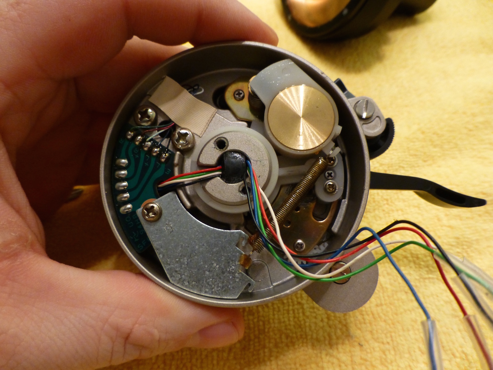

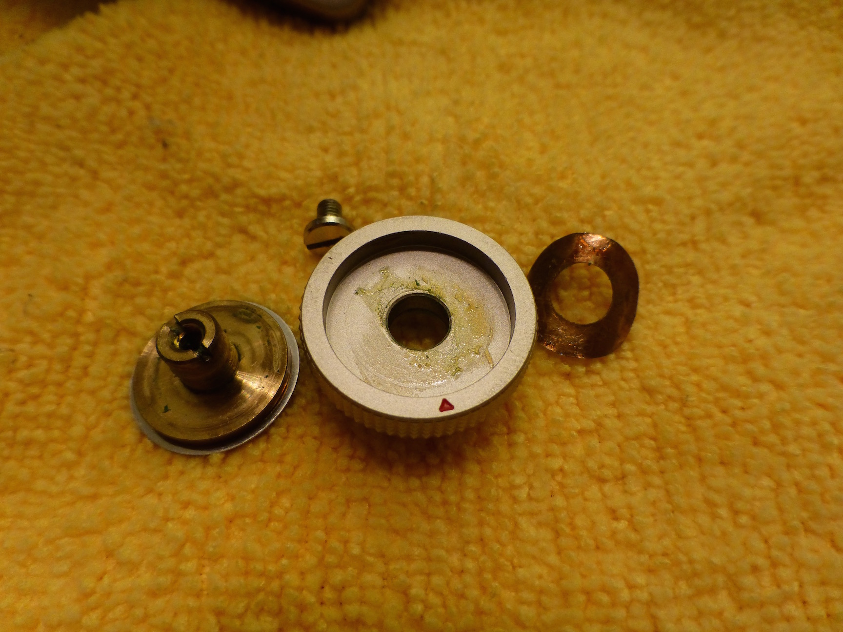
There's a screw under the dial that needs removed to lift the dial off. I cleaned mine with IPA and used a little white lithium grease before putting it back on. The actual dial is keyed and there's a stop for adjustment, so you'll need to observe those for reassembly.
There's also what I assume to be an alignment mark on the main gear. I placed it in-line with the other gears which seems to be correct. At least on my arm the setting behaves as I'd expect it to.
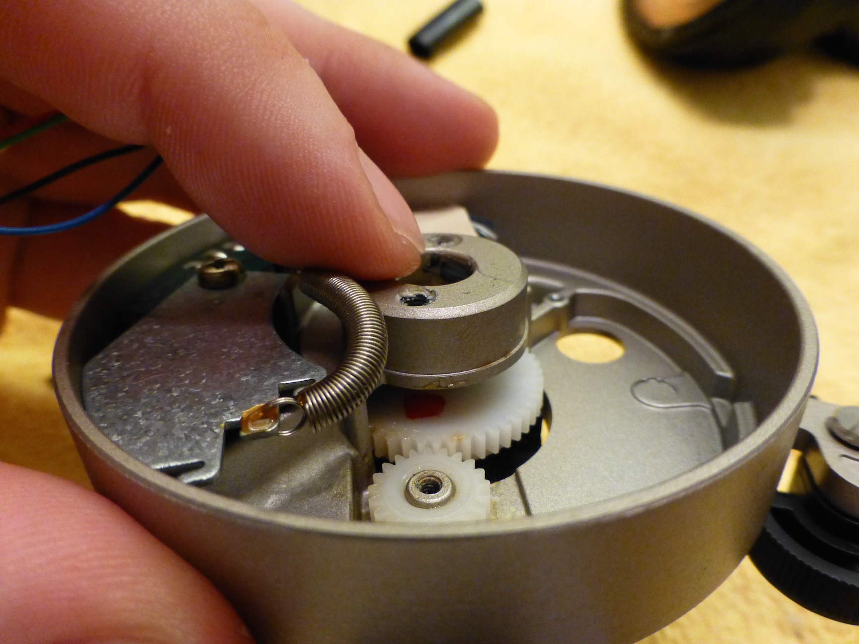
When I put the lift mechanism back in the lever would start to bind toward the up position. To fix this I loosened the three screws that hold the mechanism in the arm base, put the lever in the up position and pull outward on it, and tightened the screws. Problem solved.
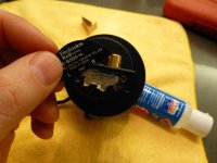
I used a dab of 5 minute epoxy on either side of the rubber block to put it back in place. As you have to tug the wires fairly tight when aligning the pillar base, the rubber block will come out if it's not glued back in.
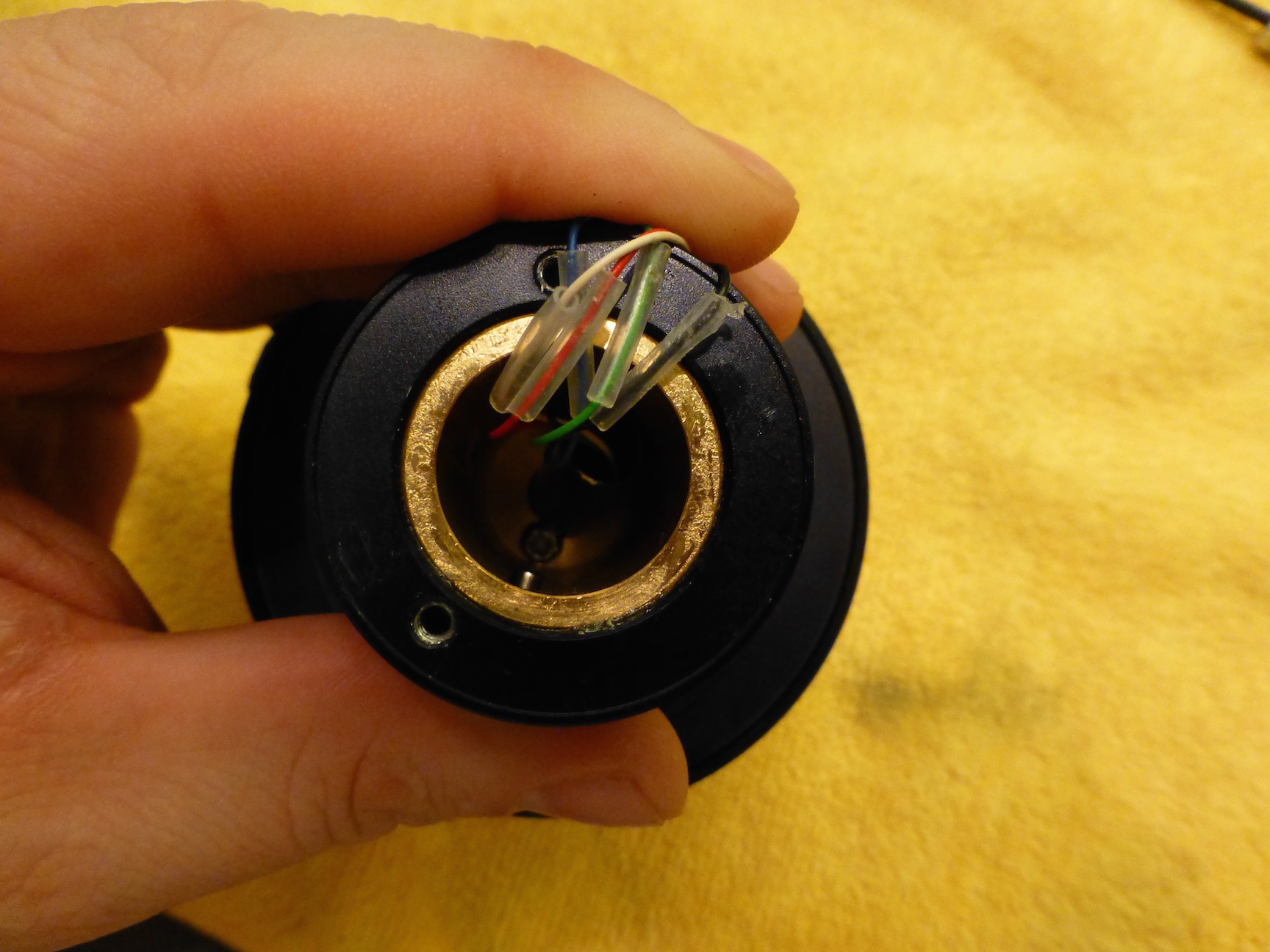
To re-solder the arm wires to the connecting block I cleaned the old solder off the tabs, and put flux on the tabs and the ends of the wires. I then loaded a little solder on the tip of my iron, held the wire to the tabs, and touched them with the iron. Done right the flux will draw the solder on to the tabs and wires and you'll have a good joint.

I stumbled across an EPA-A500 series wand I thought I'd never find, so I've been dying to give it a try. However, the anti-skate dial on my B500 base wouldn't budge, so I cracked it open last night. I wasn't able to find any information or pictures in regards to working on one of these, so perhaps this will be useful to someone down the road.
The nameplate at the base of the pillar needs removed to get in to the arm. I used a hair dryer to heat it up to soften the adhesive. Using a razor blade I was able to slowly work my way under the plate and lift it. This was an iterative process of heating and prying. You want to be careful to not scratch the paint, or bend the plate.
Remove the two larger screws and wiggle the connection block out of the pillar. You'll need to desolder the wires from the connection block.
There are two screws in the pillar that hold the pillar to the base of the arm. These have very strong thread-lock on them, so it's very important to make sure you've the correct size driver and are able to apply enough pressure to break them loose. It's quite difficult to find a good way to hold the base and do this without applying pressure to the bearings.
The two screws by the lift handle hold it in place, and three screws (one is under the spring) hold the zinc colored plate down which is the entire lift mechanism. You also need to remove the little rubber block (it's glued in, so be careful) that the wires go under, and the lift arm from the top in order to remove the lift mechanism. The lubricant-turned-glue on my arm was only at the anti-skate dial itself, so it wasn't necessary to do this.
There's a screw under the dial that needs removed to lift the dial off. I cleaned mine with IPA and used a little white lithium grease before putting it back on. The actual dial is keyed and there's a stop for adjustment, so you'll need to observe those for reassembly.
There's also what I assume to be an alignment mark on the main gear. I placed it in-line with the other gears which seems to be correct. At least on my arm the setting behaves as I'd expect it to.
When I put the lift mechanism back in the lever would start to bind toward the up position. To fix this I loosened the three screws that hold the mechanism in the arm base, put the lever in the up position and pull outward on it, and tightened the screws. Problem solved.
I used a dab of 5 minute epoxy on either side of the rubber block to put it back in place. As you have to tug the wires fairly tight when aligning the pillar base, the rubber block will come out if it's not glued back in.
To re-solder the arm wires to the connecting block I cleaned the old solder off the tabs, and put flux on the tabs and the ends of the wires. I then loaded a little solder on the tip of my iron, held the wire to the tabs, and touched them with the iron. Done right the flux will draw the solder on to the tabs and wires and you'll have a good joint.
Attachments


Last edited:
- Home
- Source & Line
- Analogue Source
- The Incredible Technics SP-10 MK3 Thread