The exponential characteristic holds quite accurately over quite a wide current range for almost any transistor. Mathematically, that means the sound of the base-emitter junction should be the same for all of them, once you scale the voltage level to account for a couple of parameters that vary from one transistor to another....claiming to have original transistors remade
In principle, then, you shouldn't need a specific type of transistor to get a specific sound in this particular circuit. Perhaps that claim has more to do with advertising than engineering?

Interesting! Robert Moog probably came up with that before JFETs were available. A very smart man, he was!the variable "resistance" in the filter is the dynamic base-emitter impedance of a transistor which varies in inverse proportion to the (DC) base current
I've seen that particular approach used elsewhere, for example, in the days of hissy cassette players. Before there was Dolby B noise reduction, there was the Phillips Dynamic Noise Limiter. The DNL circuit used the dynamic resistance of a (pair of) silicon diodes, with the current through them varied to control their resistance. (The varying current came from a rectifier circuit that was sensitive to the level and frequency of treble content on the tape. Basically, it turned down the treble when there was no treble content on the tape, reducing hiss.)
I found a schematic of the Phillips DNL online (you have to ignore some terribly fractured English text around it!):
Philip’s Dynamic Noise Limiter | Simple Circuit Diagram
A long time ago, I built the circuit shown in that schematic. Designed, etched, drilled, and stuffed my own PCB, all by hand, using some graph paper for layout, and a hand-drill, which was all I had at the time. Back then, a DIY cassette deck I'd built was my only source of decent quality music, and I built the DNL to reduce the persistent and annoying hiss. From untrustworthy memory, it worked surprisingly well on a lot of programme material.
Relevance in this thread: I wonder if the old DNL circuit would be any good as a noise-gate in a guitar amp? Might be worth a try.
Well, "good" distortion is, to a large degree, subjective. Perhaps some people would like the sound of it, who knows? Why not build and try it? 🙂I'm wondering if the circuit would give "good" distortion if it is used without the the four capacitors that make it a filter.
I'm almost sure that (a very long time ago) I once saw some sort of "enhancer" circuit that used a single silicon diode to generate small amounts of 2nd harmonic distortion, which was mixed into the music to supposedly warm and enhance it. There was no trick to it that I remember, other than keeping the signal voltage across the diode very, very small, just a few millivolts, to try and minimise the nasty upper harmonics and heavy intermodulation distortion.
I think these circuits either predate JFETs, or were designed at a time when JFETs were rare and expensive. I think diodes were used because nothing better came to mind. Perhaps I'm prejudiced, but years of disappointing experiments have convinced me that, (to my ears), trying to get good (or no) distortion from a BJT or PN junction diode is a bit like playing with a supposedly tame tiger - there is a distinct probability that things will get very ugly sooner or later! 😀
-Gnobuddy
The Moog ladder filter uses BJT's. The Steiner-Parker ladder filter uses diodes. They have a similar sound, but there are differences. The differences could be caused by the surrounding circuitry, but Moog used several different circuits to surround the "ladder' over the years. In fact the VCF circuit used in the Moog Werkstatt synth kit (2014) looks quite similar to the Steiner - Parker except for the BJT's.
The Moog VCF is known for its "fat" sound. I never thought of measuring the distortion VS frequency though.
The Moog VCF is known for its "fat" sound. I never thought of measuring the distortion VS frequency though.
For the synth fans - have you seen the 2014 documentary film "I Dream Of Wires"? I found it on Netflix, but I believe it's also available on iTunes, etc.
-Gnobuddy
-Gnobuddy
There are two versions of this film. The "hardcore" version is nearly 4 hours long. The other runs 96 minutes. Both are longer than my attention span, but I may try to watch one in short pieces when I can find it for a decent price. I have seen some of the interview material on Youtube and find some of it interesting, and some boring. Which version did you watch?
I have been "dreaming of wires" since I went to an ELP concert (or 3) in the early 70's. I started building a huge digital synthesizer with primitive RTL technology (individual gate and flip - flop chips) in 1971. I got a real engineering job that paid well in 1972, so I put my synth project on hold, and bought an Odyssey....then a few Korg's, a Solina, a couple of Rolands......I kinda had the Rick Wakeman look going back then.
Sadly all but the JV-1000 got sold over the years (life, and family happens).
My 41 year old engineering career ended about 2 years ago, so it's time to build that monster modular that I see in my dreams.
Technology has improved a bit since the early 70's, and I see no reason to build yet another Moog or ARP clone, so I have chosen my own unique route again. It is a mix of analog and digital technology, some commercial boards, some of my own design, all built around the 1V/oct standard. And, yes there are clones of certain well known modules like the Moog ladder filter. The cabinet (unfinished) holds Eurorack and RU based modules, and the "wires" are both 1/4 inch and 3.5 mm.
The big modular that I started in 1971 inside, and on top of an old Hammond transistor organ got scrapped 40 or so years ago, but I did save several of my perf board tone generators. I wonder if those 50 year old IC chips still work?
Some of the experiments will be carried out in this forum when I have something worth sharing. Right now it's just funny noises coming from a few perf board ideas, and a pile of commercial boards in various stages of completion.
Attachments
I watched part of the version on Netflix - I too ran out of attention span along the way, and never watched the entire thing.
I remember hearing "Switched On Bach" for the first time and wondering what on earth I was listening to, and I liked (still do) some of the Alan Parsons Project's songs ("Eye In The Sky" comes to mind).
But the truth is that, for the most part, the sounds that early analogue synths make don't appeal to me personally very much. I am grateful for the evolutionary lines they triggered, though - I have a sampling synthesizer in my living room right now, but it's become known to the world as an "electronic keyboard", and it mostly plays back pre-recorded samples of traditional instruments, which I could never afford or play in reality.
I can barely play the keyboard, I should add. Any real musical ability I have is on the guitar.
And then there is this, which has tempted me a couple of times: You Rock Guitar 2nd Generation MIDI Guitar | Musician's Friend
-Gnobuddy
I can barely play the keyboard
I never got really good at the keyboard either. I used to play my synths and drum machine into the 4 track Teac for backing material to play the guitar with. Now I just load a MIDI file into the sequencer and let it rip. Currently all my synths only exist in the virtual world inside my PC. I use this:
https://www.arturia.com/products/analog-classics/v-collection/overview
My parents dragged myself and both my brothers to every sort of extracurricular activities available in the late 50's and early 60's, from music lessons to Boy Scouts and sports. I was the only one that stuck to the guitar lessons, from age 9 through high school, including a couple of years playing in a surf music garage band. I, and some of my friends thought I was pretty good on the guitar.....until at age 15 I went to a Jimi Hendrix concert......After that, playing Ventures tunes in a garage band didn't look like virtuoso guitar work.
After high school I ran the service department in a stereo store that was adjacent to the University of Miami campus at the end of frat house row. The frat house closest to us was the one occupied by students from the UM School of Music. I had made friends with a few students, and got into the UM music lab a few times. They had recently acquired an ARP 2600. There are lots of cool sounds that can be made without patch cords, but going beyond those sounds requires some basic knowledge of how a synth works, and nobody, including the instructor really understood it, so I got to play with it and draw maps of how to interconnect the modules and where to set the knobs.
the sounds that early analogue synths make don't appeal to me personally very much.
The real drawback with an analog synth is the inability to store and recall settings. It can take hours of plugging wires and twisting knobs on a big synth to get a single cool sound that's usually playable only over a limited frequency range, and monophonic (one note at a time). Getting the fat sounds that are common in todays synth music requires several oscillators and multiple signal modifiers working together. It can take a rather large modular synth and a lot of tweaking to generate the sounds that are a simple preset button away on a modern plastic box. This is why the Keith Emersons and Rick Wakemans of the world needed so much equipment. What is needed is a big modular synth with complete digital programmability. I wouldn't mind taking a couple of hours to make a cool sound if there was a way to get back to it at the push of a button. It is coming, albeit slowly.
And then there is this, which has tempted me
I didn't know about that one, but there have been several attempts over the years to make a six string MIDI controller, but that one doesn't have six real strings.
I have an old Roland GI-10 MIDi guitar interface. It can be played, but has some serious limitations on what you can really do with it. I imagine that newer ones are better, but they aren't there yet.
I went to the Guitar Center a few years ago when the Fishman Triple Play came out..../better, but not perfect. I guess it's another DIY project on my list.
The way the You-Rock MIDI guitar works seems to be a love-hate thing, but you do get six strings under your right hand, letting you use all your right-hand guitar picking and plucking skills.but that one doesn't have six real strings.
Meantime the touch-pads under the left hand allow lag-free MIDI triggering - no need to wait for a few cycles of signal, then try to guess what their frequency is. It avoids many of the problems of traditional guitar synths.
Of course, you can't use left-hand vibrato, or bend the strings, because there aren't any!
To me, this thing is more like one of today's electronic keyboards, with an interface that's more accessible to me, since I happen to be able to play a guitar much better than I can play a keyboard.
The icing on the cake is the price - $250 is half the price of anything else even in the same ballpark.
Since you mentioned using all the traditional kludges for guitar backing tracks (drum machines, multi-track recorders, sequencers, MIDI tracks), I can't resist pointing out something new that has grabbed my attention quite a bit - the Digitech Trio Plus. In a nutshell, it's a new pedal that "learns" your rhythm and chord progression as you play, then chimes in with an appropriate drum pattern and bass line. It's also a looper, and if you play your progression one more time, you can loop it along with the bass and drums from the pedal.
Here's a brief demo, from one of the engineers who designed the pedal, that gives you an idea what the thing can do: https://www.youtube.com/watch?v=Q9AzLZtZ9dY
One more good demo: https://www.youtube.com/watch?v=h2KRXr8vpnI
-Gnobuddy
That's just what I was thinking. The control current is actually current through the collector (and emitter), so the base current and thus Vbe is determined by the collector current divided by beta. The original used high beta (especially for the time) transistors, and they might or might not be well matched.The exponential characteristic holds quite accurately over quite a wide current range for almost any transistor. Mathematically, that means the sound of the base-emitter junction should be the same for all of them, once you scale the voltage level to account for a couple of parameters that vary from one transistor to another.
In principle, then, you shouldn't need a specific type of transistor to get a specific sound in this particular circuit. Perhaps that claim has more to do with advertising than engineering?
This guy, in part of the big thread I link to at the end, goes into that sort of stuff:
https://www.gearslutz.com/board/11917148-post623.html
Regardless, I do wonder whether Moog got the original transistors made again. How much would it cost to do that? How many transistors would you have to buy, at a dollar each, to get it back into production? I think it more likely that a manufacturer would look for a good current part, bin it for a certain range of beta and/or other parameters, and give it a house marking for Moog. No reconstituted transistor, just one selected out of current production.
Yes indeed. This patent is from 1969, though I think he used essentially this in his modular from circa 1965:Interesting! Robert Moog probably came up with that before JFETs were available. A very smart man, he was!
Patent US3475623 - Electronic high-pass and low-pass filters employing the base to emitter ... - Google Patents
The filter's range is basically over human hearing, 20Hz to 20kHz, three decades. I doubt if jfets could be used to make a filter with that big of a range.
I actually made a crude voltage-controlled filter, it was a twin-t in an op-amp feedback loop. I replace one T's resistor to ground with a diode - increasing the DC current lowered the resistance, raising the filter frequency. It worked remarkably well, better than I expected, especially as the resistors in the other T were constant, and ideally they were supposed to be in a 2 to 1 ratio with the first resistor.I've seen that particular approach used elsewhere, for example, in the days of hissy cassette players. Before there was Dolby B noise reduction, there was the Phillips Dynamic Noise Limiter. The DNL circuit used the dynamic resistance of a (pair of) silicon diodes, with the current through them varied to control their resistance. (The varying current came from a rectifier circuit that was sensitive to the level and frequency of treble content on the tape. Basically, it turned down the treble when there was no treble content on the tape, reducing hiss.)
This was circa 1980, and it was only in recent years when I read the details on the ladder filter. Doing this (varying the DC current through a forward diode junction to vary the dynamic impedance to an audio signal) always seemed very crude to me, so I was surprised to see that the Moog filter did this.
Yes, that's why I put good in quotes. This filter will give (mostly, depending on how well things are balanced and matched) symmetrical distortion, though a lot of "good" guitar distortion is of the single-ended variety.Well, "good" distortion is, to a large degree, subjective.
I just might.Perhaps some people would like the sound of it, who knows? Why not build and try it? 🙂
I'm almost sure that (a very long time ago) I once saw some sort of "enhancer" circuit that used a single silicon diode to generate small amounts of 2nd harmonic distortion, which was mixed into the music to supposedly warm and enhance it. There was no trick to it that I remember, other than keeping the signal voltage across the diode very, very small, just a few millivolts, to try and minimise the nasty upper harmonics and heavy intermodulation distortion.
There was the original Aphex Aural Exciter circa 1975 that did something like that, but I don't know if that's the exact way it made its distortion. I remember the Eagles "The Long Run" album cover made a point that the album was made WITHOUT using it.
Apparently, others used diodes in their filters to avoid infringing on Moog's patent that used transistors.The Moog ladder filter uses BJT's. The Steiner-Parker ladder filter uses diodes. They have a similar sound, but there are differences. The differences could be caused by the surrounding circuitry, but Moog used several different circuits to surround the "ladder' over the years. In fact the VCF circuit used in the Moog Werkstatt synth kit (2014) looks quite similar to the Steiner - Parker except for the BJT's.
The Moog VCF is known for its "fat" sound. I never thought of measuring the distortion VS frequency though.
I've been reading (and sometime posting as benbradley in ) this popular thread on the new Minimoog. It's mostly non-technical, but there's the guy i mentioned above who apparently has studied every component in the thing (and there's also a lot of online technical analysis of the Moog Ladder Filter):
https://www.gearslutz.com/board/ele...c-production/1086408-new-moog-minimoog-d.html
Is there interest in a synthesizer design thread?
I finally found a couple of free hours to tinker with my amp. Unfortunately, it turned out to be one of those days when nothing sounds right.
I tried two different guitars, lots of different control settings, low gain, high gain, bright cap in, bright cap out, master volume up, master volume down, this, that, and the other. And, you know what, in the end, it all sounded like poo.
Eventually I disconnected my entire preamp section, ran a guitar straight into a Danelectro Fish n Chips (a 7-band graphic EQ plus clean boost), and ran that straight into the power amp section of my circuit.
At least that exercise did teach me something: a little cut at 400 Hz got rid of the excessively midrangey sound I'd been hearing with one of my guitars. And, with this speaker and this guitar, at least, things sounded better with a treble boost starting at 400 Hz and climbing all the way to 6.4 kHz, which is the highest frequency slider on the Fish n Chips.
I've never seen that much treble boost sound good in a guitar amp before. Either I have an unplanned heavy treble roll-off somewhere else in the amp or speaker, or I've gone stone deaf overnight.
I guess I may also want to look into adding an adjustable mid-cut tone control to the circuit.
I must say, it's a little depressing when a solid-state EQ pedal turns out to be a better-sounding preamp than the valve-based preamp I've been designing and building, a bit at a time, for months!
I hope there will be a happy turn-around next time I tackle this thing, but for tonight, I shall admit defeat, and slink off with my tail down, to find something less challenging to do.
On the plus side, I found out something that should have been obvious: a graphic EQ pedal is an excellent tool to help voice a new guitar amp design. It would seem that once you've found an EQ curve that sounds good, you can then synthesize it into the preamp.
Which means I really need to be able to measure frequency responses quickly, so I can find out what the EQ is actually doing, and replicate it with resistors and caps. Another project to deal with!
-Gnobuddy
Is there interest in a synthesizer design thread?
It might work. There are plenty of ideas to kick around, and I figured that I would start one once I had something useful to contribute.
As with guitar amps, there are several definitions of the term "synthesizer." Pure analog, hybrid, or digital. MIDI, CV or both, V/oct or V/Hz... Each has their strong supporters and haters. At this time, I would say anything goes.
I have been tinkering with synthesis off and on since about 1970. My ultimate dream is a polyphonic synth (6 note) small enough to fit inside a guitar. If an when it becomes a reality it will probably be a hybrid analog/digital design.
the Digitech Trio Plus.
That IS a cool toy. If I had $300 to spare right now I'd buy one.
it turned out to be one of those days when nothing sounds right.....it's a little depressing when a solid-state EQ pedal turns out to be a better-sounding
Sometimes I spend days simulating and calculating, then prototyping an amp and then.....tossing it in the trash, or worse. One of the amps I built for this challenge went through a lot of changes before it became Amp 1.5 that I like and still use often even though it still sits on the corner of my bench naked. I still haven't made a cabinet for it. The bare PC board and transformers are connected to a speaker cabinet, my guitar, and a line cord......
It started out as amp 1.0, a self split amp designed to run from about 135 volts derived from a tube rectifier and an isolation transformers. It sounded bad, dull lifeless, and rather wimpy. Nothing I did to it made it sound good, so I decided to kill it by turning the power supply up till it melted.....only it started to sound good. The little amp sounded OK (but not stellar) on about 300 volts.....but the tubes are rated for 150 V max on the plates, 135 V max on G2. They were glowing rather brightly.....
Several iterations, simulations, later.....an extra gain stage instead of the tube rectifier, 170 volts of B+, a big resistor on the screens for a "sag" effect, totally new single knob tone control.....Amp 1.4 is done, and I left it at that for the conclusion of the challenge. It still didn't rock.
A few years later I find the old amp, and decide that it's still not an amp that I want to play. I had done enough thinking, and trying to "engineer" an amp.......time for the old "George" method.....A box full of parts, a bag full of clip leads, a hand full of pots, a couple of those "forbidden" black plastic silicon tubes, and two days of playing with the parts.....finally, it ROCKS!
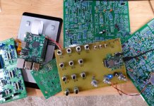
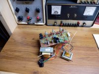
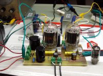
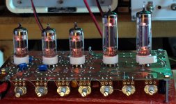
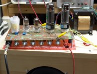
Amp 1.5 is the last of that design. I see no need to change it any further. I do however see a continuation of that concept. That little amp has character, now it needs a bit more power, and maybe two preamp channels.....
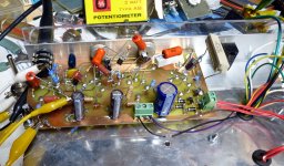
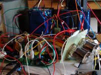
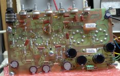
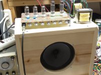
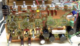
The first picture shows Amp 1.5 as it exists now. Picture 2 shows the "play with parts" method I used to get there. Picture 3, well people told me that you can't design an amp this way. Picture 4 shows the finished prototype, a small HiFi amp.
Attachments
Printer2, you win the "Man of fewest words" award! 😀
George, I have never seen quite that complex a rat's nest build added to an existing PCB! 😀
Makes you wonder about all the amp builders who can only work from a physical layout, doesn't it? Without a mental picture of the schematic in your head, you simply can't do what George does.
I am trying to engineer an amp, and not always getting it right, partly because I have very limited experience with valves. I haven't tried very much of the "informed tinkering" approach, for the same reason - I'm not that well informed, yet.
Oh, I know how to design a functional textbook audio amp stage with a valve, and what all the components do, and so on. But this whole business of making good-sounding distortion - I still have a lot to learn in that area.
Two things are bugging me most at the moment: One, at a particular amount of overdrive, there is a nasty-sounding additional distortion that suddenly appears, and I haven't managed to track down where it's coming from. Two, why does my amp need that much treble boost to sound good? There must be something causing excessive treble roll-off somewhere, and that too needs to be tracked down and fixed.
As for the Digitech Trio+, they are even more expensive in Canada ($425 plus taxes
 ). The price of a decent electric guitar or amp, actually.
Still, I'm going to get one of these at some point. It's been quite a few years since I had any gifts for Christmas or my birthday, because I didn't actually want anything. The Trio+ has changed that - I want one, because I think this may be the best guitar practice tool I've ever run across, and I think it will help me become a better musician if I work with it.
It would be much cheaper (and much more fun!) to actually play music with other competent musicians from whom I can learn and improve, but I haven't had too much luck making that happen, yet. So it's going to have to be the little trio of robots Digitech stuffed into their Trio+!
-Gnobuddy
George, I have never seen quite that complex a rat's nest build added to an existing PCB! 😀
Makes you wonder about all the amp builders who can only work from a physical layout, doesn't it? Without a mental picture of the schematic in your head, you simply can't do what George does.
I am trying to engineer an amp, and not always getting it right, partly because I have very limited experience with valves. I haven't tried very much of the "informed tinkering" approach, for the same reason - I'm not that well informed, yet.
Oh, I know how to design a functional textbook audio amp stage with a valve, and what all the components do, and so on. But this whole business of making good-sounding distortion - I still have a lot to learn in that area.
Two things are bugging me most at the moment: One, at a particular amount of overdrive, there is a nasty-sounding additional distortion that suddenly appears, and I haven't managed to track down where it's coming from. Two, why does my amp need that much treble boost to sound good? There must be something causing excessive treble roll-off somewhere, and that too needs to be tracked down and fixed.
As for the Digitech Trio+, they are even more expensive in Canada ($425 plus taxes
Still, I'm going to get one of these at some point. It's been quite a few years since I had any gifts for Christmas or my birthday, because I didn't actually want anything. The Trio+ has changed that - I want one, because I think this may be the best guitar practice tool I've ever run across, and I think it will help me become a better musician if I work with it.
It would be much cheaper (and much more fun!) to actually play music with other competent musicians from whom I can learn and improve, but I haven't had too much luck making that happen, yet. So it's going to have to be the little trio of robots Digitech stuffed into their Trio+!
-Gnobuddy
I just found a 1 megohm gate stopper attached to the LND 150 MOSFET in my amp. 😱
How did that happen? Looking at the layout, I can see my blunder. I was working from a schematic in my head, and along the way, I changed my mind about where the incoming signal was going to be injected. And then I forgot to change the 1M resistor to suit. 😱
The LND 150 is supposed to only have 10pF input capacitance, so a 1M gate stopper might not actually do too much damage - that's a 16 kHz corner frequency. Still, it wasn't what I intended, so out came the 1M resistor, and in went a 22k one.
I have a small pentode driving the MOSFET phase-splitter. To avoid nasty-sounding solid-state clipping, I have a fixed voltage divider between the two stages, set up so the pentode clips and maxes out it's output signal without being able to drive the MOSFET into clipping.
I thought perhaps I'd made a mistake with the resistor values, and that's where the occasional nasty distortion was from. Nope, added more attenuation there, still get the nasty noises. Fiddled with the gain, master volume and the L-pad, aha, the nasty-sounding distortion is still there with gain up and master volume down. That distortion is coming from somewhere in the preamp.
Maybe I can track that down tomorrow. For now, it's 1AM, so I better get to bed.
-Gnobuddy
Teasing us? ......Printer2, you win the "Man of fewest words" award!
Not quite enough words to figure out who or what he is referring to.
George, I have never seen quite that complex a rat's nest build added to an existing PCB!
I have done worse. I usually have a design in mind. I lay out a PC board, sometimes with just the basic idea in place, then add, cut, paste and hack away at it with flying parts, clip leads, additional PC boards or whatever to make it work, or I give up. Whatever is left over goes into the "box of broken dreams." I may get a new idea later down the road, and often these old boards form a place to start from. If I come up with a workable design, I lay out a new board and the process repeats.
This is an offshoot from the way we did things at work. I was a two way radio and cell phone designer at Motorola for 41 years. A cell phone can go through 10 to 20 board iterations before it becomes a product, and several more after it goes into production to improve quality or reduce costs.
In this case Amp 1.0 started out as a minimalistic design to prove a point....Yes it was a playable guitar amp with about $25 worth of parts in it, and it would have been sufficient for a person practicing or who liked a clean clear tone....I kept hacking, adding stuff, ripping stuff out and tweaking until amp 1.5 was the result. What the forum didn't see was the five different PC boards (1.0, 1.1.....) and the rats nest on each one to get there. Amp 1.0 had 4 tubes, a rectifier, a pentode preamp, and two output tubes. There was a 3 tube version, then three more 4 tube versions.
The clip lead rats nest seen in the last two pictures was an idea for a simple spud amp that was hatched and turned into a working amp in a single day with clip leads and a dead Tubelab SSE board. I drew up a paper schematic and laid out the PC board while on an airplane ride, made it when I got back, and it worked.
Sometimes I go the other direction. Amp 2.0 started out as an exercise in how to use all of the $100 parts budget to make a screamer. The schematic is in post #1760. I put every idea that I wanted to try into the schematic and laid out a board, actually there were two versions. One used the UL84, a series string version of the 6CW5, which is very similar to the EL84, and the other used an octal sweep tube. The schematics were identical except for the tubes being used. I started with a "Marshall 18 watt" schematic that I got off the web. I used tubes that had about half as much gain as a 12AX7, so I added a couple of gain stages and put a mosfet follower between each stage.
In that case many if the "wild idea" parts are not installed in the initial build. The minimum parts to make a working amp are installed, often one stage at a time until I am happy with the results, then the ideas get tested, one at a time. The amp had far too much gain, so most of the mosfets came out, and I removed a gain stage.
I liked the UL84 version a lot. It made about 20 watts cranked, and had a good tone.
I never got the sweep tube version working exactly right. In a moment of madness, I hacked the PC board to fit some EL34's and TV tuner tubes, connected it to a 400 volt power supply, and "tested" it with a real OPT.....Yes, the design screams and cranks out nearly 50 watts....there is hope for it yet. Note the "damper" on the first preamp tube and padding under the board. It was so microphonic that feedback occurred.
The sweep tube version has been found, but I haven't seen the other one in a few years. It's got to be here somewhere. I plan on revisiting it once I find it. Maybe amp 1.5 and amp 2.3 will meet with a rats nest together to make something really cool.
First three pictures are of the UL84 version with all of the parts installed.
The next three show the sweep tube version. Note all the empty holes in the board. It was built after the first board was debugged, so that all the stuff that didn't work, was never installed.
Attachments

Not quite enough words to figure out who or what he is referring to.
Hard to figure out if I was commenting on previous posts, otherwise the default would be the last post. Well, telling use the journey you took to find your nirvana and providing no details. I guess I could have gone back in time trying to find out what you had for each circuit but way too many pages. Pretty sure everyone including yourself has an interest in how others solve problems. Hearing that you are satisfied with your circuit is wonderful, not much more to add to that I guess.
I'm never really satisfied with anything, but that's the engineer in me. My life long journey has been learning to know when something is good enough. As a kid making guitar amps, if it worked at all, didn't blow up, made something that resembled sound, and lived long enough for me to make another, it was good. The requirements have gotten tougher as time goes on.
When working in a product group at Motorola (designing products to be sold commercially) the goals wound be well documented before work started, and negotiated in some rather ugly design review meetings at the product took shape. After the first run of product is made there are weeks to months of tests that must be passed, depending on the market. A police radio where someone's life is on the line goes through far more testing than a cell phone that will be obsolete in a year.
Things were a bit more undefined in the research group where I worked for the last 10 years of my career. The boss says, "figure out how to test this new IC chip we are developing", or "design it into something so we can sell it to the product groups."
I put amps that will wear the Tubelab name through my own test cycle, including electrical torture testing, and assembly by people who are not versed in electronics. I make a few and loan then out to see what happens. Some do not make the cut, and go through some revisions or quietly disappear. The little HiFi amp shown as a furball of clip leads above was copied by another member of this forum and offered for sale on his web site before I had finished testing it because I was dumb enough to post the schematic. I tossed my amp in the trash and sold all the parts for it. I have had to be a bit more quiet about designs I may turn into products later because of that incident.
This challenge got started because a person showed up on this forum several years back bragging that he had designed the best tube guitar amp that could be made for some low budget number (I don't remember how much it was now). I replied "wanna bet" and this thread got started. He was adamant that there be NO silicon in the signal path, and despite decisions to the contrary early on by the thread starter, I decided to respect that edict for Amp 1.0
I had thought at the time that I would make a Tubelab guitar amp kit from the amp, which would be "so simple even your drummer could build it." That means it has to be simple, foolproof, and not operate on 400+ volts! Trust me, that turned out to be the hard one. Getting a good "cranked" sound from 135 volts of B+ isn't easy. In fact I couldn't do it, so out went the rectifier tube, and in went a hand full of diodes. B+ was now 170 volts. This was now Amp 1.1.
There still wasn't enough gain and max power was still just short of 2 watts. A single output tube would make 1.5 watts, the self split design wasn't working good. And I didn't like the tone control.
Amp 1.2 got another stage, a triode with a Mu of 100 was wired in between the input pentode, and the output stage. I tried it as a PI, and as a simple gain stage. Both concepts had their merits. I sat down with a bunch of parts and played until I had a rather strange single knob tone / distortion control.
The tone control was implemented on a new PC board which was called Amp 1.3.
There was some issues with a faint hum or buzz that had appeared when the extra gain was added, so a couple of caps were changed, and one was added to the half wave DC heater supply. The PC board was changed to allow a separate ground return for the heater current. This became Amp 1.4, and that's where the challenge ended.
I still wasn't fully satisfied with the amp. It needed more gain, and I knew that those two output tubes should give me at least 3 watts, since a single tube made 1.5 watts. The challenge ended, I lost my job, and had to leave Florida on 3 weeks notice. We had lived in the same house for 37 years, try moving all that stuff 1200 miles on three weeks notice.
Amp 1.4 Amp 2.3 an its brother got tossed into random boxes, which have been moved 3 or 4 times into one of 3 storage locations. There are lots of things that I still can't find.
Amp 1.4 turned up in a box of books, and I started playing with it. No more "challenge" no more rules.....stick in a couple of mosfets, and the amp is now the screamer that I always wanted. One mosfet is now the PI. With a proper PI to drive each output tube, I get 4 watts and the screen supply which feeds the preamp sags better than the tube rectifier ever could.
The second mosfet is a buffer / bootstrap on the input tube. With it came a new knob, the saturator knob. It allows the first stage gain to be adjusted from about 5 to over 500, with minimal microphonics. Amp 1.5 is born!
Amp 1.5 is called "done" because I can't find any more ways to improve it without major design changes. I now believe that it is the best it can be within the two design constraints left on it. There were some design constraints imposed by the challenge. The $100 parts limit, was not a real issue. I believe that I could make something better with more B+, but that will be a different design.
I hope this explanation helps. Let me know if there is any interest in a stage by stage analysis of how it works, or a better blow by blow rebuild / do over on Amp 2.3 once I find it.
I'm still playing with the idea of making Amp 1.5 into a Tubelab kit, or PC board. Any thoughts / interest?
When working in a product group at Motorola (designing products to be sold commercially) the goals wound be well documented before work started, and negotiated in some rather ugly design review meetings at the product took shape. After the first run of product is made there are weeks to months of tests that must be passed, depending on the market. A police radio where someone's life is on the line goes through far more testing than a cell phone that will be obsolete in a year.
Things were a bit more undefined in the research group where I worked for the last 10 years of my career. The boss says, "figure out how to test this new IC chip we are developing", or "design it into something so we can sell it to the product groups."
I put amps that will wear the Tubelab name through my own test cycle, including electrical torture testing, and assembly by people who are not versed in electronics. I make a few and loan then out to see what happens. Some do not make the cut, and go through some revisions or quietly disappear. The little HiFi amp shown as a furball of clip leads above was copied by another member of this forum and offered for sale on his web site before I had finished testing it because I was dumb enough to post the schematic. I tossed my amp in the trash and sold all the parts for it. I have had to be a bit more quiet about designs I may turn into products later because of that incident.
to find out what you had for each circuit but way too many pages.
This challenge got started because a person showed up on this forum several years back bragging that he had designed the best tube guitar amp that could be made for some low budget number (I don't remember how much it was now). I replied "wanna bet" and this thread got started. He was adamant that there be NO silicon in the signal path, and despite decisions to the contrary early on by the thread starter, I decided to respect that edict for Amp 1.0
I had thought at the time that I would make a Tubelab guitar amp kit from the amp, which would be "so simple even your drummer could build it." That means it has to be simple, foolproof, and not operate on 400+ volts! Trust me, that turned out to be the hard one. Getting a good "cranked" sound from 135 volts of B+ isn't easy. In fact I couldn't do it, so out went the rectifier tube, and in went a hand full of diodes. B+ was now 170 volts. This was now Amp 1.1.
There still wasn't enough gain and max power was still just short of 2 watts. A single output tube would make 1.5 watts, the self split design wasn't working good. And I didn't like the tone control.
Amp 1.2 got another stage, a triode with a Mu of 100 was wired in between the input pentode, and the output stage. I tried it as a PI, and as a simple gain stage. Both concepts had their merits. I sat down with a bunch of parts and played until I had a rather strange single knob tone / distortion control.
The tone control was implemented on a new PC board which was called Amp 1.3.
There was some issues with a faint hum or buzz that had appeared when the extra gain was added, so a couple of caps were changed, and one was added to the half wave DC heater supply. The PC board was changed to allow a separate ground return for the heater current. This became Amp 1.4, and that's where the challenge ended.
I still wasn't fully satisfied with the amp. It needed more gain, and I knew that those two output tubes should give me at least 3 watts, since a single tube made 1.5 watts. The challenge ended, I lost my job, and had to leave Florida on 3 weeks notice. We had lived in the same house for 37 years, try moving all that stuff 1200 miles on three weeks notice.
Amp 1.4 Amp 2.3 an its brother got tossed into random boxes, which have been moved 3 or 4 times into one of 3 storage locations. There are lots of things that I still can't find.
Amp 1.4 turned up in a box of books, and I started playing with it. No more "challenge" no more rules.....stick in a couple of mosfets, and the amp is now the screamer that I always wanted. One mosfet is now the PI. With a proper PI to drive each output tube, I get 4 watts and the screen supply which feeds the preamp sags better than the tube rectifier ever could.
The second mosfet is a buffer / bootstrap on the input tube. With it came a new knob, the saturator knob. It allows the first stage gain to be adjusted from about 5 to over 500, with minimal microphonics. Amp 1.5 is born!
Amp 1.5 is called "done" because I can't find any more ways to improve it without major design changes. I now believe that it is the best it can be within the two design constraints left on it. There were some design constraints imposed by the challenge. The $100 parts limit, was not a real issue. I believe that I could make something better with more B+, but that will be a different design.
I hope this explanation helps. Let me know if there is any interest in a stage by stage analysis of how it works, or a better blow by blow rebuild / do over on Amp 2.3 once I find it.
I'm still playing with the idea of making Amp 1.5 into a Tubelab kit, or PC board. Any thoughts / interest?
I'm not surprised. IMO, the whole "self split" concept is fundamentally and terribly flawed, in multiple ways. It was a bad idea at the start, and hasn't become any better for having been used surprisingly often in DIY builds....the self split design wasn't working good.
Firstly, self-split doesn't work at all unless both output devices are operating in class A; if in class AB or B, as soon as one device cuts off, there is no drive to the second. Bye bye, push-pull, hello, no output signal whatsoever!
Secondly, "self split" is basically another way of saying "a really poorly designed differential amplifier stage". A self-split output stage is actually a differential amp with a very "short tail" instead of the "long tail" it needs to actually function well.
As everyone on this thread surely knows, a differential stage works best with a constant current source setting the sum of the two currents; a sufficiently large resistance is a passable substitute, at the cost of reduced balance between the two outputs, and reduced CMRR.
But a really small tail resistance? Ridiculous, that's what it is! You get very mis-matched signals, and no CMRR. But, in a self-split output stage, the resistance has to be small, otherwise you won't get any real power delivered to the load.
So, you have your choice: either a horribly out-of-balance output stage, or an output stage that can't deliver any power to speak of. What a wonderful choice, huh?
Since I'm a gnobuddy, my word doesn't exactly carry a lot of clout, but my advice to the world is to "Just say no!" to the whole "self-split output" concept. It doesn't work well, and it never will!
-Gnobuddy
.love to hear a recording of Amp 1.5 if you have it
I don't have anything yet, but it's on my to-do list.....crappy iPAD recordings don't count.
I just grabbed a 32 input Mackie mixing console for $200, but I don't have a place to put it yet. A Shure SM-57 (as soon as I find it) direct into my PC's sound module should be doable.
the whole "self split" concept is fundamentally and terribly flawed
I fully understand the suckyness of the concept, and as you said, a CCS with plenty of voltage headroom, and class A only is the only way to make it work. I had never tried a self split, and doubt that I will try it again, but I needed a push pull design to avoid DC in a $4 OPT that wasn't meant to be an OPT, and I didn't want to waste a tube on a PI that doesn't contribute any gain. A 50 cent mosfet is a different story.
I will try nearly anything once, I tried it, it sucked big time. Maybe it has a place somewhere, but not in my amps......The Oddwatt HiFi people obviously have a different opinion, some good magic, and a CCS in the output tube's tail.
Regardless of marketing noise, there isn't a guitar amp alive that runs class A. It might be biased at the edge of meltdown with a conservative load line, but plug in an overdrive pedal, set the controls to 11, and hit it, goodbye class A. One or more output tubes will be driven to cutoff, saturation or both.....unless it has a really inadequate preamp and PI design.
Since I'm a gnobuddy, my word doesn't exactly carry a lot of clout
Many of us can figure out who knows what they are talking about, and who is blowing smoke.....or selling snake oil! All technically correct opinions are equally valid until proven wrong.....which is nearly impossible in the audio world. Remember all the noise about silicon corrupting the sound of a guitar amp earlier in this thread.
- Home
- Live Sound
- Instruments and Amps
- The Hundred-Buck Amp Challenge