the ones that look like 1/4 watt resistors - do seem to have a + on one end. Those may be tantalum, I suppose.
There used to be some mustard colored tantalum caps in a package like that. They were often seen in 60's and early 70's vintage military and industrial equipment.
I don't like them because they fail at the slightest exceeding of their specs and fail closed
Yes, tantalum caps usually fail to a short, and will often burst into flames if in a circuit capable of delivering some current. They must also be de-rated if operated in high temperatures or high current applications.
I was a design engineer on the early iDEN (Nextel, Southern Link, MiKE, Telus, Clearnet) phones. The tantalum bypass caps on the 3.6 volt B+ supply line to the RF Power Amp had to be 16 volt caps to avoid flaming failures due to the high pulse currents drawn by the PA. They were replaced with 6.3 volt ceramic when good high "K" ceramics became available.
I'm still pondering the "mostly software" vs "mostly analog hardware, with just enough digital and software to run it" approaches.
I have been chipping away at both ends of that game for a very long time. I guess it depends a lot on what you really want to do.
If you just want a test system for testing audio amps (gain, power output, distortion, frequency response, harmonic spectra....) it's hard to beat a PC. Get an old Windows PC, a 24/96 sound card, and some free software like RMAA, and you are set. Test out your system by plugging its output to its input and running distortion and frequency response tests. With a 24 bit, 96 KHz sound card you should be below .05% distortion with frequency response from 10 Hz or so to 40 KHz.....
If you want to tinker with the Arduino platform, the Teensy is a good place to start. It is currently the best tradeoff between $$$$, size, and raw processing power.
The graphical audio design tool makes things almost easy, and there is a "high resolution sine wave" generator block that claims to "Create a highly precise, low distortion sine wave signal. Mainly useful for codec & analog circuitry testing." "An 11th order Taylor series approximation is used to generate a very accurate sine wave. At least the upper 25 bits are believe to be perfect. This is mainly intended for testing 24 bit codec chips!" I haven't tried the Hi-Res sine wave since the standard version is perfect for my needs.
Have a look at the "Teensy Audio Tutorial and Workshop" video. I saw that, and bought a couple of Teensys and Audio boards. Then I built the exact hardware that they used in the tutorial on a proto board, and followed all the examples. From there it was cut and paste code from the tutorial examples, some code I downloaded from the web, and from the Arduino library. Yesterday I added a rotary encoder to my breadboard, and today I will try to read it using example code from the Teensy web site. Eventually I want to build a simple synthesizer small enough to put INSIDE a guitar. I think that the Teensy is the enabling technology for doing just that.
I haven't done much coding for microcontrollers, which is one reason I was thinking about the Arduino, with its large community and relative ease of use.
After Nextel was killed off by Sprint, and Motorola sold their cell phone business, I migrated to the IC design and development team. I used the ChipKit Arduino compatible boards for some of my IC testing projects at work. Those were basically "mostly analog hardware, with just enough digital and software to run it" designs. The ChipKit just opened and closed relays and programmed the IC under test via the SPI interface.
20 years ago the Nextel phone business was the biggest electronics operation in south Florida. Most of the chip vendors handed out free samples to us like candy on Halloween. I used some audio chips, SPI programmed graphic equalizer, SPI programmed audio preamp, and a pair of 75 watt chip amps, from National Semiconductor, and a PIC chip from Microchip to make a programmable guitar amp. It's main feature is that you could spin the knobs to get a sound that you liked, then save it in a memory location in the PIC chip. All of the analog signal processing was done inside the analog chips. Unfortunately, it just didn't sound like a guitar amp should sound. It was too clean until you really leaned on it, then it transitioned to nasty real quick.
It got robbed for parts, but I am still planning to do a tube amp version.
On the "mostly software" side of that coin, the "DSP in a stomp box" guys have been making slow steady progress toward decent sounding simulations. They have come a long way since the Zoom 505 I got back in the 90's. I can plug my guitar directly into my PC through the audio interface, then wire the output of the PC's interface into a tube "HiFi" amp, and dial up a tone anywhere from the reverb laden "60's surf music" to "full metal racket." The results are good enough that I have a PC based guitar amp under construction. This was prompted primarily because of the cool looking case I found in a Goodwill thrift store though.
Right now, my guess is that the Teensy is not powerful enough to bring the "mostly software" setup inside the guitar, but there are guitars out there with Kaossilators and Launchpads in them. Soon we will have the technology to put a whole Windows or Linux PC inside a guitar with a full blown modeling system.
I think a simple Teensy based synth, or possibly one monophonic synth per string, would be cool, and not too far beyond my skill set.....there is only one way to find out.
That sentence describes 99.9% of all solid-state guitar amps I've ever encountered. 😀It was too clean until you really leaned on it, then it transitioned to nasty real quick.
I think many analog audio design engineers have not fully realised the connection between having lots of negative feedback, and having an abrupt transition from "way too clean" to "way too harsh".
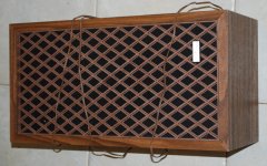
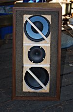
I have an elderly friend, David, with a physical handicap that makes it very hard for him to handle anything heavy. His passion is playing guitar (clean tones most of the time) and singing. I am slowly piecing together a relatively solid-state guitar amp as a surprise gift for him, starting with a vintage Sears "Adequate-Fi" speaker from a thrift store, and a little class-D audio power amp from Parts Express.
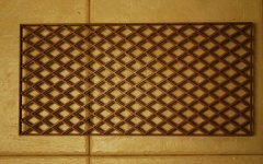
The vintage Sears speaker has a diamond-pattern plastic grille that reminds me of period Vox guitar amps. That was one of the reasons I bought it for David's project.
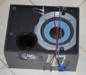
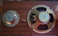
The power amp is stereo. One channel runs the original woofer/tweeter combination that was in the Sears speaker. I've hacked in a third loudspeaker driver into the box, run off the second amp channel. That driver was the mid/woofer in an incredibly ugly plastic boombox speaker from the same thrift store. It sounds decent as an electric guitar speaker. (A few pics attached.)
As far as the rest of the electronics goes, part one of the plan is to build a simple mic preamp, mated to the woofer/tweeter channel, so David can run his vocals through it.
Part two is to build an electric guitar preamp with JFETs, which will be encouraged to gradually produce smooth, low-order harmonic distortion. The JFET guitar pre will drive the other channel, and the other (single) speaker.
My hypothesis is that separating the guitar and vocal channels completely (both electronically and acoustically) in this way will allow undistorted vocals to coexist with (slightly) distorted guitar.
If it all works out, it should serve triple duty as small vocal P.A., acoustic guitar amp, or electric guitar amp, while remaining small and light enough for David to cope with. Deep bass and extreme loudness will, of course, be sacrificed to make this possible.
David won't accept a gift if it costs much, I'm quite sure. That's why the thrift-store and low-buck approach. Who knows, maybe it will qualify as a hundred-buck amp too, though entirely solid-state, and with one-off thrift-store parts in the mix.
This has been on hold for many months because of lack of free time, but that is about to change soon.
Perhaps a Raspberry Pi 3 running Guitarix on a stripped-down Linux distro, paired with a cheap class D power amp module, would also qualify as a hundred-buck guitar amp. 😀The results are good enough that I have a PC based guitar amp under construction.
The fastest, lightest Linux distro I've encountered in recent years is Tiny Core Linux. I've run it successfully on 200 MHz Pentium PCs that I kept out of the landfill for over 12 years, all the way till 2014, serving as Internet kiosks for community college students.
Tiny Core Linux now has an ARM port for the Raspberry Pi. I have high hopes that this might make a Pi 3 actually usable as a multimedia micro-PC. Haven't tried it yet, though.
The sad truth, though, is that I have spent far too much money on digitally modelled guitar gizmos over the last 15 years, and come away unsatisfied every time. Currently I have a Zoom G3. I find some of the FX and modelled stomp-boxes usable, and the built in looper is very handy for noodling around at home. But the distortions, overdrives, fuzz-boxes, and amp simulations all leave me with severe ear-fatigue and a dull headache very quickly. Most also sound harsh to me.
For whatever reason, my ears are more forgiving of digital amp modelling at lower frequencies. I have a Zoom B3 (for bass guitar) that sounds acceptable to my ears. I just dabble in bass, though, perhaps my ear is simply not developed enough, and a real bass player might hear problems that I do not.
I have no philosophical objection to the concept of modelling at all, in fact I would be thrilled to have a light, reliable, affordable solid state guitar amp that sounded as good as a good valve amp. The problem is just that my ears and brain are not happy with what is currently on the market, especially at the affordable end of the spectrum.
Considering that commercial attempts at digitally modelled guitar amps go back to at least the 1980s, I'm not holding my breath for a breakthrough any time soon. Digitally modelled guitar amps are like cheap energy from controlled fusion. In both cases, we've had literally several decades of promises about imminent breakthroughs. In both cases, the breakthroughs have not yet materialised!
On the other hand, a valve guitar amp, with digipots controlled by a little microcontroller to make it possible to save settings for gain, tone, etc - that sounds like a very interesting project! (But not one I'm about to try, I'm already up to the elbows in unfinished projects!)
-Gnobuddy
Attachments
-
 02_vintage_Sears_speaker_600px.jpg124 KB · Views: 236
 -
 01_ugly_woofer_600px.jpg128.1 KB · Views: 241
 -
 06_grille_removed_600px.jpg126.9 KB · Views: 236
 -
 04_woofer_tweeter_600px.jpg87.9 KB · Views: 239
 -
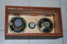 08_speakers_in_box_B_600px.jpg112.7 KB · Views: 227
 -
 09_speakers_in_box_C_600px.jpg122.8 KB · Views: 83
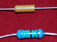
After a few attempts I have a passable photo of one of the mysterious (to me) tan capacitors, next to a 1/2 watt metal-film resistor for comparison.
So, is this a tantalum electrolytic? If it is, I'll stop using them. I didn't know about their tendency to fail early, and fail short-circuit.
Thanks in advance!
-Gnobuddy
So, is this a tantalum electrolytic? If it is, I'll stop using them. I didn't know about their tendency to fail early, and fail short-circuit.
Thanks in advance!
-Gnobuddy
Attachments
Thanks for the suggestion, and the mention of RMAA, which I'd somehow completely overlooked.If you just want a test system for testing audio amps (gain, power output, distortion, frequency response, harmonic spectra....) it's hard to beat a PC. Get an old Windows PC, a 24/96 sound card, and some free software like RMAA, and you are set.
The catch is finding appropriate sacrificial hardware. I moved to BC from the USA two years ago, and left behind as much "stuff" as I could, including lots of old PC hardware. Here in BC, I find people are less likely to chuck old PC hardware out simply because something newer is available. In other words, even old Core 2 Duo hardware is worth something on Craigslist, more than I want to spend right now.
On the plus side, I'm pretty sure I did bring my original Microsoft Windows XP Pro CD. So if I find the right PC hardware (and keep it off the Internet completely), I have the operating system RMAA was designed for.
I am no longer interested in building Hi-Fi stuff, just the odd guitar amp. So I don't need the ability to measure down to 0.0005% THD. On the other hand, I think the ability to see distortion spectra from a guitar amp might prove to be useful.
Speaking of Hi-Fi, a few weeks ago I found a Yamaha RX-360 stereo receiver in a thrift shop, priced at $19.99. It's now in the spare bedroom, along with a $7.99 Sony DVD player from the same shop. The DVD player is actually used to play CDs, not DVDs.
Both components are old but work flawlessly, and the DVD player has RCA audio outputs to mate with the RCA input jacks on the Yamaha amp. No need to mess with oddly temperamental HDMI interfaces.
It's almost ridiculous - superb audio electronics for under thirty bucks! But nobody wants traditional audio components any more, so they can be found dirt cheap in the thrift stores every now and then.
(The catch, of course, is getting hold of equally good speakers.)
-Gnobuddy
So, is this a tantalum electrolytic?
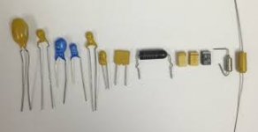
Yes, it is. There are several varieties of packaging, yours is one of the least common. Your parts are from 1985. See picture.
Similar parts are still being made today.
T322C106K025AT Kemet | Capacitors | DigiKey
If it is, I'll stop using them.
Actually there is no reason to trash them. Tantalum caps are regarded as quite reliable, and having lower inductance than other types, so they were often used in military applications, and other high spec circuits. Tantalums have fallen out of favor since the "great tantalum shortage" in about 2000. At that time there was only one active mining source for raw tantalum. The cell phone boom in the late 90's sucked up all the available tantalum creating a shortage. Within a year a 10 cent capacitor went to over a dollar in million unit quantities, and there were 52 week lead times. This forced parts vendors to accelerate the development of non-piezoelectric high K ceramics. Now we have ceramic caps that are cheaper, and of higher electric quality. Tantalum caps have however, not gone away. There are still plenty of applications where they are a good fit.
All capacitors are made of two conductors separated by an insulator. A modern dry capacitor usually fails by one of two ways. One of the connections breaks and it goes open circuit. This happens, but isn't too common. A "wet" type capacitor (most electrolytics) will eventually dry out and go open, although modern electrolytics are much better than old ones, heat is their enemy, and many are rated for as few as 1000 hours of operation at their maximum temperature.
The insulator can break down and the cap shorts out. This is the usual failure mechanism for most types of capacitors. If the capacitor is in a circuit where a high current can flow when it shorts out, bad stuff can happen with ANY type of capacitor. Ceramics and some electrolytics explode. Newer electrolytics have a safety vent. When they short out, they spew their stinky corrosive goo all over your amp. Tantalums explode or burn, not because of the tantalum, but because of the potassium oxide cathode....it is flammable.
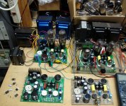
I wouldn't use a tantalum in a high current circuit, say across an unfused B+ line, but they are useful for cathode bypass caps, and impart a slightly different sound than a similar sized electrolytic. I enclosed a picture of several Tubelab TSE HiFi amps. The very first prototype in in the lower right corner. Note there are tantalum (small blue cap) and electrolytic (large light blue can) capacitors wired in parallel for the cathode bypass caps on the preamp tubes.
Attachments
That's quite an adventure story (about the tantalum shortage)!
I have something interesting to share with those of you still on this thread. Take a look at the attached screenshot showing LTSpice doing its thing with a passive tone control circuit.
The circuit is a heavily tweaked version of the Voight tone control presented in Merlin Blencowe's valve preamp book. I have tweaked almost every component value to get the circuit to behave the way I prefer. Centre frequency is now about 700 Hz (bang in the centre of the 80 Hz - 6KHz guitar frequency band on a logarithmic frequency axis).
A few points to note:
Looking at it another way, when we use $1 valves, voltage gain is cheap. We don't need to penny-pinch and minimise the total number of valves, as Leonidas Fender used to. That means I can focus on getting the timbre I want, without worrying about every last decibel of insertion loss.
I've mocked up a version of this tone control (a rats-nest build right on the pot tags). I tested it with my guitar amp, and I love it!
IMO, this is the way guitar amp tone controls should operate - with the same ease of use and predictability as an active Baxandall tone control circuit on a Hi-Fi amp. Just turn the bass knob to adjust (only) the bass, turn the treble knob to adjust (only) the treble, and you're done!
You don't have to fuss around endlessly because the "treble" knob mucks up the bass, and the "bass" knob mucks up the volume, and the "volume" knob mucks up the treble, and round and round and round you go. None of that "interactive" garbage that came from sheer bad circuit design.
Ease of use isn't just nice, it's really important to me as a musician. To be a good musician, I have to try and stay in a more creative, right-brain-dominant state of mind. If I have to stop and think about how to operate confusing interactive tone controls, that pulls me into a left-brain-dominant thinking state. No good music performance comes from a left-brained thinking state!
-Gnobuddy
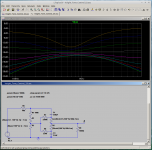
I have something interesting to share with those of you still on this thread. Take a look at the attached screenshot showing LTSpice doing its thing with a passive tone control circuit.
The circuit is a heavily tweaked version of the Voight tone control presented in Merlin Blencowe's valve preamp book. I have tweaked almost every component value to get the circuit to behave the way I prefer. Centre frequency is now about 700 Hz (bang in the centre of the 80 Hz - 6KHz guitar frequency band on a logarithmic frequency axis).
A few points to note:
- R6 represents the output resistance of the valve feeding the tone control. 40k is typical for a 12AX7 with a 100k anode load.
- R9 represents the 1-megohm grid bias resistor of the valve fed by the output of the tone control. It loads down the tone control a bit.
- The frequency response curves you see include the effect of R6 and R9. So this is how the circuit will behave when actually inserted in your amp's signal chain.
- R2+R3 is the bass potentiometer (1M).
- R4+R5 is the treble potentiometer (250k). Representing each pot with two resistors in this way, lets me trick LTSpice into "twiddling the knobs" for me, and making multiple frequency response plots for various settings.
- The circuit consists of only three resistors and two capacitors, in addition to the two potentiometers.
- The frequency response is extremely flat with both (log) pots centered. If your guitar amp sounds good without a tone control, this circuit won't ruin that when you add it to the signal chain.
- The controls are almost completely independent of (as opposed to interactive with) each other. This is how tone controls are supposed to work! It is extremely easy to dial up the tone you want.
- There is about 18-20 dB insertion loss.
Looking at it another way, when we use $1 valves, voltage gain is cheap. We don't need to penny-pinch and minimise the total number of valves, as Leonidas Fender used to. That means I can focus on getting the timbre I want, without worrying about every last decibel of insertion loss.
I've mocked up a version of this tone control (a rats-nest build right on the pot tags). I tested it with my guitar amp, and I love it!
IMO, this is the way guitar amp tone controls should operate - with the same ease of use and predictability as an active Baxandall tone control circuit on a Hi-Fi amp. Just turn the bass knob to adjust (only) the bass, turn the treble knob to adjust (only) the treble, and you're done!
You don't have to fuss around endlessly because the "treble" knob mucks up the bass, and the "bass" knob mucks up the volume, and the "volume" knob mucks up the treble, and round and round and round you go. None of that "interactive" garbage that came from sheer bad circuit design.
Ease of use isn't just nice, it's really important to me as a musician. To be a good musician, I have to try and stay in a more creative, right-brain-dominant state of mind. If I have to stop and think about how to operate confusing interactive tone controls, that pulls me into a left-brain-dominant thinking state. No good music performance comes from a left-brained thinking state!
-Gnobuddy
Attachments
Excellent, please share your opinions with us here after you've tested the circuit!
-Gnobuddy
-Gnobuddy
So, is this a tantalum electrolytic? If it is, I'll stop using them. I didn't know about their tendency to fail early, and fail short-circuit.
Thanks in advance!
-Gnobuddy
All electrolytics have the same failure potential. Nothing wrong with "tants", and I use 'em for RF and digital applications since these have way lower stray inductance. I don't use 'em in audio applications since tants have wonkier D/E characteristics than aluminum electrolytics that can have sonic consequences.
Harmonic distortion is usually of no consequence in RF service. The main exception is a plate modulated AM, Class C final, but that's also an audio application. For a plate modulator, the best tubes are the low-u, power triodes, same as audio finals. For digital, all you need to know is if your signal line is high or low, and signal distortion is of no consequence there at all.
Thanks for your input, Miles! George has already convinced me that I don't need to chuck my tiny tantalum caps. 🙂
My (very) preliminary experiments with guitar amps suggest that 10% (mostly) second harmonic distortion still sounds very "clean" to a guitarist. Anything less than, say, 3% second harmonic distortion starts to sound "too clean", like a solid-state amp. And for the more extremely overdriven sounds in some contemporary music genres, the output is almost a square wave, and the concept of total harmonic distortion starts not to make very much sense any more.
Contrast that 10% with the 0.001% THD of, say, some of Douglas Self's designs; we're talking at least four orders of magnitude more (intentional) distortion in the guitar amp! Literally, more than ten thousand times as much distortion.
Because of this, I think issues like capacitor distortion are pretty much completely irrelevant when it comes to guitar amps. As far as I can tell from the skimpy data I've found, capacitor-induced distortions are several orders of magnitude below the distortion from the valves, transformers, speaker, and speaker enclosure in a guitar amp. Which means it is utterly impossible to hear the distortion contribution from the capacitors.
So I quite happily use ceramic (and now tantalum) caps in my guitar electronics signal chain. There are no audible consequences whatsoever, not even the microphony issues I remember from ceramic caps two or three decades ago.
I do care about reliability, though, and I have zero previous experience with tantalum caps prior to buying this bag of surplus ones, so I was concerned. But you and George have put me at ease in that regard. (Though George also pointed out that my tantalum caps are over 30 years old!)
-Gnobuddy
I was discussing more music reproduction amps where you definitely don't want any electrolytic directly in the signal path. There, it definitely makes an audible difference. Guitar amps are a whole 'nother story where "tone" is distortion. If that's what you're designing, capacitor distortion would be irrelevant.
Age can be a possible problem... or not. I have a couple of Al electrolytics that I salvaged from a radio from the 1930s. These are Mallory electrolytics that are so ancient they are packaged in cardboard, not the more familiar metal cans. Both these are still good, showing no appreciable leakage. I could definitely use 'em after some preliminary reforming to make certain they're still ~10uF, and could stand up to the voltage.
I have an equally old PIO capacitor (glass tube with metal end caps) in one project connected across the HV secondary of the PTX to help prevent poofage of the solid state diodes from flyback voltages from the filter inductor on power down. That one is still going strong nine years later. Likely, your 30 y/o tants are OK.
I do care about reliability, though, and I have zero previous experience with tantalum caps prior to buying this bag of surplus ones, so I was concerned. But you and George have put me at ease in that regard. (Though George also pointed out that my tantalum caps are over 30 years old!)
-Gnobuddy
Age can be a possible problem... or not. I have a couple of Al electrolytics that I salvaged from a radio from the 1930s. These are Mallory electrolytics that are so ancient they are packaged in cardboard, not the more familiar metal cans. Both these are still good, showing no appreciable leakage. I could definitely use 'em after some preliminary reforming to make certain they're still ~10uF, and could stand up to the voltage.
I have an equally old PIO capacitor (glass tube with metal end caps) in one project connected across the HV secondary of the PTX to help prevent poofage of the solid state diodes from flyback voltages from the filter inductor on power down. That one is still going strong nine years later. Likely, your 30 y/o tants are OK.
Wow, I finally made it all the way through this thread. I was originally drawn here looking for a PP EL86/6CW5 guitar amp design. It was very worthwhile to go thru the whole thread for me. I've been down many of these same paths myself, and often was not as resourceful as most of you are in figuring things out. I've got most of my stock from free or low cost tube junk items. Lot's of very nice vintage Mullard/Amperex tubes. That's what the EL86's I have are Mullard made in Gt Brittan or Amperex made in Holland. Using lower voltage to get more watts than you could from the EL84, can lead to a less expensive PS. I even have bought the cheap Chinese DC step up converter. I have messed around with it some and have not found any problems with it drawing enough current to run a PP EL84 circuit. I was just trying to use it with 6V tubes and I feed the converter with a 19VDC Dell laptop PS. I think I could go down to 12VDC input and still get my +400VDC output. That would allow me to use all 12V tubes easily like Printers 12AQ5/12AX7 design. Well, he's still got that 6AU6 in there I guess I'd have to change to 12AU6. I'd love to see any EL86 designs you guys have, and will try to constructively contribute ideas/successes/failures in the future.
Best regards,
Paul
Best regards,
Paul
Paul, welcome!
Do you by any chance have a link to the DC-DC converter you used? I don't think most models can handle 19V input, so I'm interested in the one you used. I too have a couple of unused laptop power supplies waiting for a project to use them.
-Gnobuddy
Do you by any chance have a link to the DC-DC converter you used? I don't think most models can handle 19V input, so I'm interested in the one you used. I too have a couple of unused laptop power supplies waiting for a project to use them.
-Gnobuddy
Thanks for the link! That 12 unit survived 19 volt operation?Laptop bricks can supply plenty of current to run this and the heaters. 😀
Nineteen volt laptop bricks would be perfect if we used three of each kind of valve in our circuit, and ran each group of three identical 6.3V heaters in series. All we need now is a three-valve output stage design. 😀
-Gnobuddy
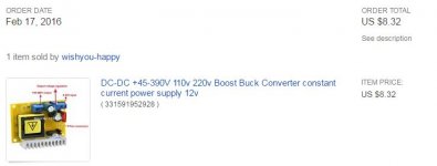
It says it can go to from 8-35VDC input.
No issues found at 19V.
It did output up to 400VDC with 19V in no problem.
Less than $9 delivered is hard to beat.
No issues found at 19V.
It did output up to 400VDC with 19V in no problem.
Less than $9 delivered is hard to beat.
Laptop bricks can supply plenty of current to run this and the heaters. 😀
You have almost made a sale. How do you adjust the voltage out? How about the max current? Some more options.
15CW5 / PL84
8CW5 / XL86
10CW5 / LL86
Last edited:
Adjustment made with the pot, of course. LOL
Current is stated to decrease with increased output voltage, and lower input voltage and current.
It didn't seem to have any problem powering a PP EL84 Hoffman Stout circuit with the 19V input. The Dell bricks I have all have excess current capacity. I suspect most laptop bricks do also because they need that to recharge the laptops battery.
I'd like to have other DIYers experimenting with this and reporting their successes and failures so I don't have to figure them all out on my own. LOL
I think this is the same item, on Amazon.ca. Twice the US price, of course, typical of Amazon.ca: https://www.amazon.ca/C-J-SHOP-Conv...1_fkmr0_1?ie=UTF8&qid=1463454390&sr=8-1-fkmr0
The voltage adjustment (trim)pot can just be seen, it's a light blue rectangular lump. But it's unrecognizable as to function simply by looking at it, because the adjustment screw is not visible in the photos.
For those of us in Canada, I also notice that this week Canadian Tire has a 75 watt, 110V, power inverter on sale at $16 or so. Their printed add lists it under the brand name "Eliminator", the website lists it under "Motomaster".
That inverter should be good for maybe 160V DC. Enough for some of those radio valves designed to run without a power transformer, but not for 12AX7's and their friends. Anyone want to make a guitar amp with a pair of push-pull 12C5 outputs? 🙂
-Gnobuddy
I was originally drawn here looking for a PP EL86/6CW5 guitar amp design.
I designed and built two amps for this thread. Amp 1.4 used 100 mA series string radio tubes and made about 2 watts. It was intended to be a usable guitar amp for minimum $$$. One of the main arguments in this thread was the use of silicon in the signal path. I asked the question early on and it was allowed, but hotly debated throughout the thread. For this reason Amp 1.4 had no silicon other than for rectification. It worked, but didn't inspire me to turn it on every day and wound up getting tossed into a random box when I had to pack up everything and move it all twice for a total of 1200 miles.
This thread had fallen into a six month deep sleep when I found amp 1.4 in a box while looking for some parts. Curiosity convinced me to plug it in, which led to how can I make this thing ROCK!!!!!! That led to amp 1.5 which, despite of a cabinet still gets played nearly every day.
At the time of the active challenge, I also had two other amp projects. Both were higher power designs with some mosfet followers used as buffers to bring the gain of a TV / radio tuner tube into 12AX7 territory. The design was inspired by the "Marshall 18 Watt" schematic floating around the internet.
Both fit into the "under $100" parts budget, including the attenuator used to reduce the power output for practice amp use, while allowing full metal racket tone from overdriven output tubes. The "twins" were identical except for the output tubes. One used 2 X UL84 / 45B5's and the other used 2 X 50JY7 sweep tubes. Both used 3 X UCC85 / 26AQ8 preamp tubes. The sweep tube amp never quite worked right so, of course that's the one I have recently found.
The 45B5 is a 45 volt 100 mA heater version of the 6CW5. The power supply was a SS diode rectified 120 VAC isolation transformer which delivered 170 VDC. There was also a voltage doubler to make 340 VDC. The heaters were all wired in series and connected to the 170 VDC supply, as were the output tube screens. The output tube plates and the preamp tubes were fed from the 340 volt supply. The OPT was a 50 VA power (mains) toroid creating about a 3200 ohm CT load. The amp made 25 clean watts, and about 30 watts at clipping. Played through a single 8 inch Jensen alnico speaker, it screamed.
I thought the schematic was somewhere in that long thread, but I could not find it last night. It is included here. There were many changes sky wired into the amp that were never documented and put into the schematic. Most were deletions. All of the mosfet shunts on the preamp tube cathodes are gone. The idea was for variable gain, but it didn't work. The whole amp had far too much gain, so most of the mosfet buffers were removed, and I believe one gain stage had been removed. I won't really know until I find the amp. The PI and output stages work great and didn't need mods. I now believe that the pentode / mosfet saturator that I added to amp 1.4 to make amp 1.5 will go into this design.
Attachments
Last edited:
- Home
- Live Sound
- Instruments and Amps
- The Hundred-Buck Amp Challenge