That sounds like fun, looking forward to seeing/hearing more about it!Nope. Working on my pp EL91 with ECF80 preamp using 100v line trafo for OPT, all powered by a 12vac wall wart and cased in a trade-aid jewellery box 🙂
And VVR'd with a 25c Thai IRF820 off eBay.
I envy you the 100V line transformer. The 70.7 V ones available in North America don't give you quite the same stepdown ratio or reflected primary impedance.
-Gnobuddy
I'm sorry to hear that. I hope you feel better soon.Been sick for a few weeks.
It has been a miserable flu season here in BC. I was sick continuously for over two months in late 2015, and then sick again in 2016. At my workplace, everywhere you go - even now at the tail end of March - you see people who look too sick to be out of bed wandering around, coughing, wheezing, sniffling, and looking quite miserable.
I am glad you are exploring the FET angle. I too have thought about that (but never got off my behind and did anything about it). Keep the drain voltage constant (cascode, say) and theory predicts mostly 2nd harmonic distortion - that might be a way to get good-sounding clean tones. Then again, don't keep the drain voltage constant, and you might get just the right amount of additional harmonics as the drain-source voltage drops towards saturation on signal peaks. Who knows?
I have thought about the switching supply for B+ too, but I think I will take the easy way out rather than try to build my own. I found some cheap 48V switching supplies in a surplus store, and am thinking about stringing three of them in series (on the DC side) to get roughly 150V, and designing a tube amp to work off that. These have the 48V DC output completely isolated from the mains neutral, so I can't think of a good reason why the outputs can't be connected in series.
I'll have to wait at least another month for work to ease up before I can tackle any new projects, though. Right now all I can find time for is to report on stuff I've done - very slowly - over the last two years.
-Gnobuddy
That sounds like fun, looking forward to seeing/hearing more about it!
I envy you the 100V line transformer. The 70.7 V ones available in North America don't give you quite the same stepdown ratio or reflected primary impedance.
-Gnobuddy
A preview is in the thread "Lo budget, good sound" dated 5 June 2014 (p34 Instruments & Amps)
Last edited:
Thanks for the link! I just read through the thread.A preview is in the thread "Lo budget, good sound" dated 5 June 2014 (p34 Instruments & Amps)
I agree with you about the TMB tone control circuit. Politely put, after having built and tried out one, I have a very low opinion of it. It's hard to believe something this ineffective and hard to use became a widely-used standard across multiple brands. Cheap is king, evidently, as minimal parts count is about the only thing going for this awesomely awful circuit.
When did "interactive controls" supposedly become a good thing, anyway? Imagine if the steering wheel and accelerator on your car were "interactive", so you got wild acceleration every time you turned left, and dropped to an idle every time you turned right? Is there anybody nutty enough to think that would be a good thing? As far as I'm concerned, "interactive controls" are synonymous with "poor engineering".
I haven't tried the "tilt" control (aka Big Muff tone control), though I've heard good things about it from a few creditable sources.
I'd like to have the predictable and precise nature of the active Baxandall tone contol widely used in Hi-Fi, without the problems that would occur (in a guitar amp) if you allowed an active circuit with lots of negative feedback to become overdriven. (Can you say "harsh clipping"? 😱 )
The obvious candidate is the passive Baxandall circuit, but to me it isn't particularly appealing, as the curves show it loses much of the near-ideal behaviour of the active version.
I have been tinkering in LTSpice with the Voight tone control mentioned in Merlin Blencowe's book, and I think it shows a lot of promise, though there is at least one fairly big problem I have to solve before I can be satisfied with it.
-Gnobuddy
Printer2's mini (2 watt) 5e3 was one of my early inspirations. I started out trying to duplicate his output stage.
Here's the funny part, while his amp sounds glorious overdriven, mine sounded horrible, with the same output stage. I had lot's of blocking distortion, and none of the rich overdrive tone.
It took me a long time to get rid of the horribleness, and by the time I'd succeeded, my output stage no longer sounds anything like Printer2's. Now mine is relatively polite, even when overdriven, without the in-your-face raucousness of Printer2's original.
I have a feeling my output stage design ended up taking on aspects of my personality as a guitar player - I'm not exactly the raucous, in-your-face type as a musician, and my amp evolved to suit the way I play it.
Just another reason why guitar amp design is proving to be much more fun than traditional audio. As in the world of art, there is no single right way to do it!
-Gnobuddy
Started out as a P-P Champ, sort of.
Had a 12AQ5 P-P amp with mosfet PI that I put in a small chassis and was planning on putting it in a narrow panel Tweed Champ cabinet. Had it with volume and tone control controls along with a switch that I used to change the NFB. Eventually I tried adding a bass control that could be switched in that was to replace the NFB switch.
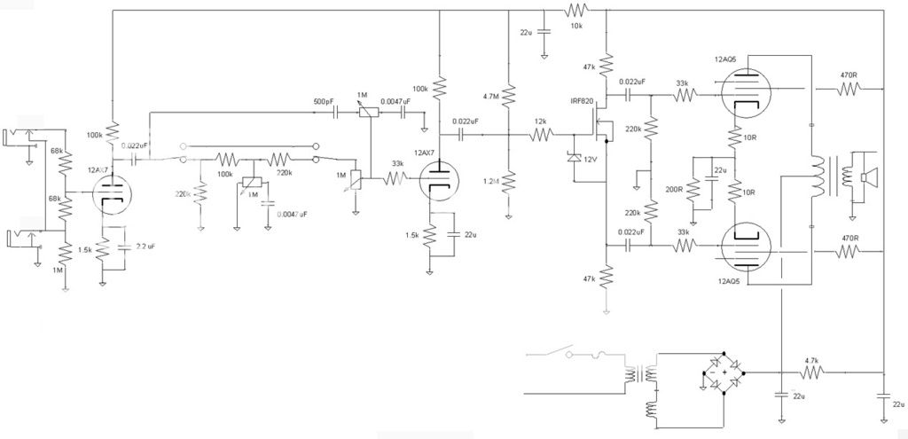
Found it did not do too much, mind you both the tone and bass control should have entered the top of the volume control, I had the tone (treble) still hooked up as the treble bypass Tweed style. So it got me thinking along a convoluted path which got me to the following schematic. The first stage using the LND150 or 2N5485 with the first stage of a BSIAB. I have not decided which way to go, going to have to breadboard both as the two drawings I pulled together from posts on the web.
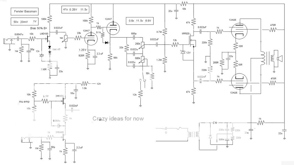
Have some numbers that are a little useful (to me at least). Looked up some Fender schematics and came up with the gain of a 57 Bassman RI sections using the Amp's service manual voltages. Input is voltage gain of 50, second stage 41, the tone stack -0.6. The PI has a gain of >1 and the 12AQ5's need 15V for full output. First stage should have more than enough gain with the second stage biased at 1.25V. The second stage gain of 41x being hit with a 1V signal should put out 40V. Cut that in half through the tone stack and you have 20V to the 12AQ5's.
So depending on tone stack positions the second stage should start to clip around roughly when the outputs do. Have the amp running on 240V right now (Tweed tone controls separating two triodes) but am thinking of going with a voltage doubler for roughly 300V with the transformer being rewired. Have a 70V transformer for the output, if I am lucky I would guess 7W out of it. Just want a small practice amp out of this one and using it to try out something different.
Not as simple an amp as a BF Champ, hoping to cover a lot more sonic ground with this one. Not much more in part costs, still using a 70V like transformer and a 120V isolation transformer. Using a wallwart switching power supply for the heaters.
Had a 12AQ5 P-P amp with mosfet PI that I put in a small chassis and was planning on putting it in a narrow panel Tweed Champ cabinet. Had it with volume and tone control controls along with a switch that I used to change the NFB. Eventually I tried adding a bass control that could be switched in that was to replace the NFB switch.
Found it did not do too much, mind you both the tone and bass control should have entered the top of the volume control, I had the tone (treble) still hooked up as the treble bypass Tweed style. So it got me thinking along a convoluted path which got me to the following schematic. The first stage using the LND150 or 2N5485 with the first stage of a BSIAB. I have not decided which way to go, going to have to breadboard both as the two drawings I pulled together from posts on the web.
Have some numbers that are a little useful (to me at least). Looked up some Fender schematics and came up with the gain of a 57 Bassman RI sections using the Amp's service manual voltages. Input is voltage gain of 50, second stage 41, the tone stack -0.6. The PI has a gain of >1 and the 12AQ5's need 15V for full output. First stage should have more than enough gain with the second stage biased at 1.25V. The second stage gain of 41x being hit with a 1V signal should put out 40V. Cut that in half through the tone stack and you have 20V to the 12AQ5's.
So depending on tone stack positions the second stage should start to clip around roughly when the outputs do. Have the amp running on 240V right now (Tweed tone controls separating two triodes) but am thinking of going with a voltage doubler for roughly 300V with the transformer being rewired. Have a 70V transformer for the output, if I am lucky I would guess 7W out of it. Just want a small practice amp out of this one and using it to try out something different.
Not as simple an amp as a BF Champ, hoping to cover a lot more sonic ground with this one. Not much more in part costs, still using a 70V like transformer and a 120V isolation transformer. Using a wallwart switching power supply for the heaters.
I like the working title on your (2nd) diagram. Crazy and creative usually live very close to each other. 🙂
Compared to valves and BJT's, biasing FETs for linear operation is always a bit of a headache because of the huge parameter spreads in Idss and Vp. Since you're using (12V?) DC on the heaters, there is an interesting possibility: connect the +12 end to ground, so the other end becomes a (-12V DC) power supply rail.
Now you can bias N-channel FETs by tying the gate to ground, and using a "long tail" source resistor to the -12V rail to set source current. Changes of a volt or two in Vgs due to manufacturing tolerances will now have much less effect on Is, because a 1-2 volt change on top of 12-15 volts is a relatively small percentage change. Hey, 17% spread in Id is much better than the typically 300% spreads in the raw FET parameters!
Depending on the output valves you use, a -12V rail may also be enough for fixed-bias. If you ever get the urge to change your 2W mini 5E3 output stage to fixed bias, this would make it easy. (No idea how it would sound, though, probably not much like a 5E3!)
Switching topics entirely, I spent some time tinkering with a 6LX8 triode/pentode for preamp use. It looks promising, the triode section biased up nicely to about 1 mA anode current with a 1.5k cathode resistor, 82 k anode load, and around 190V B+. These values are for roughly centre-bias (symmetrical clipping, which is probably not going to produce the best tone, but it's a starting point.)
My 'scope thinks the triode stage small-signal voltage gain is around 50 (34dB), with no loading on the output, and the cathode bypassed with a 3.3uf ceramic cap. That's more gain than I was expecting for this rather low ra (20 k) triode. Datasheet mu is 70, though, so a gain of 50 is certainly not impossible.
The pentode section of the 6LX8 biased up to around 1.2 mA (cathode current) with 1k Rk, 47k Ra, 270k Rg2 (from B+ to the screen grid), and about 135 volts B+. The relatively low B+ voltage is to control the voltage gain, which, I hope, will help me avoid those dreaded pentode microphonics problems.
Once again, these values aren't fully optimised. The pentode section is a bit cold-biased now, the output clips on positive half-cycles well before negative ones. Ra may need to be increased, unless cold-biasing turns out to produce the desired tone.
I have no time to tinker with this any more for a few days, but it would be fun if this $1 tube turns out to have some good sounds in it. Brief initial tests suggest the triode may be ultra clean (maybe because Ra is so much bigger than ra, almost like operating it with a constant current source anode load.) Not necessarily what we want for guitar, but maybe with a lower B+ and lower Ra?
-Gnobuddy
Thought of doing the 12V fixed bias with the 12AQ5's in the amp but I will be upping the voltage to about 300V by rewiring the output transformer and using a voltage doubler. Think the bias will be around -15V then.
Picked up another PT, a woman from work brought in an old radio for me to part out, the only thing worth keeping was the PT and the OT. So I have a pretty good collection of PT's. Will I ever use them I don't know now. I am dipping my toe in the SMPS pool, hoping to build a 350-400V supply, maybe for a pair of 6V6's. Find some light pine, aluminum chassis (only sturdy enough to carry the OT), a neo speaker. Have your cake and eat it.
Picked up another PT, a woman from work brought in an old radio for me to part out, the only thing worth keeping was the PT and the OT. So I have a pretty good collection of PT's. Will I ever use them I don't know now. I am dipping my toe in the SMPS pool, hoping to build a 350-400V supply, maybe for a pair of 6V6's. Find some light pine, aluminum chassis (only sturdy enough to carry the OT), a neo speaker. Have your cake and eat it.
Hang onto them, I think audio output transformers are very much an endangered species now....So I have a pretty good collection of PT's.
I'm amazed (and thankful) that those 70V audio line transformers are still being manufactured. But I wonder how long that will continue. The death knell may be sounding: a young chap I know recently told me he had just installed a set of new speakers in his truck - and each speaker came with its own individual Class-D power amp mounted right on the magnet!
Obviously, you supply 12V DC power to each speaker's onboard chip amp, and drive the thing with a line-level signal from the stereo head in the car/truck.
This was for an automotive application. But how long before PA and paging systems adopt the same technology? A low-wattage class-D chip amp is probably cheaper to manufacture than an audio line transformer now.
Good luck with the SMPS supply, the line-powered ones are scary. Please wear eye, face, and hearing protection (I'm entirely serious here - those things explode caps quite violently if things go wrong.)
I know you have a family member who happens to know quite a lot about SMPS, that's a great asset, and I am rooting for you to succeed. (I think power transformers are also an endangered species now, at least at power levels below a kilowatt or so.)
Speaking of a light aluminum chassis - am I the only one who longingly eyes those strong, light, aluminum serving-trays at the A&W fast-food joints? 😀
(I found that Presidents Choice Superstores in BC sell the same aluminum trays, by the way.)
-Gnobuddy
Crazy and creative usually live very close to each other.
Both live inside my head, constantly fighting for control......some days one wins out, other days it's a draw and nothing good gets done.
am I the only one who longingly eyes those strong, light, aluminum serving-trays at the A&W
I haven't seen an A&W in a long time.
Yesterday I had to take my daughter to a dental clinic about 150 miles away for surgery. She has wanted to visit IKEA since she moved here, so we stopped in on the way. They had some nice aluminum baking pans that would fit several amp designs, but I got distracted by the stuff in the as-is section and forgot to buy one....next time. Did get a nice 30 X 50 inch rolling wood table with a few scratches for $20 though. I had to borrow some tools and disassemble it to get it in the car.
Good luck with the SMPS supply, the line-powered ones are scary.....I'm entirely serious here - those things explode caps quite violently
My line powered experiments ended with mosfets turning to dust at a very rapid rate. I learned to put an inverted large heavy coffee mug over them before switch on. After blowing up a whole bag of FET's I have moved on to things powered by 24 volts or less.
It's rather simple to get a 12 volt 6 amp brick from Amazon for $10 and use it to power a 240 volt power inverter. Steal the 300 volts DC from inside the inverter to use as B+, and use the raw 12 volts to light the tubes. Simple and cheap power supply. Feeds a 30 watt guitar amp, no problem. The cheap, unregulated inverters have a nice output sag that works great on a cranked guitar amp.
I am going to give myself five tries at the SMPS. Got two packages in the mail today.
Hard to believe one of the cores could do a pair of 6V6's in P-P.
Hard to believe one of the cores could do a pair of 6V6's in P-P.
I bought one of the cheap SMPS off of ebay that's supposed to take 12-18 volts and output 200-450. I say supposed to because the magic smoke came out on power up. Now it will start at 350v but drop to 200v under load. Probably not even worth trying to fix, but I'd like to know that a new one won't self-destruct.
When I was a young boy, I was fascinated - and also scared - by fireworks. One time I tried inverting an empty tin can over a small firework, thinking it might reduce the scare-factor.My line powered experiments ended with mosfets turning to dust at a very rapid rate. I learned to put an inverted large heavy coffee mug over them before switch on.
It did the opposite. Much louder, much more scary, and it redesigned the shape of that tin can, not to mention blasted it several feet into the air. Let's just say I got an object lesson in what happens if you try to contain an explosion!
I should probably mention that fireworks were common, in that time and place. Our attitudes are very different today!
Back to guitar amps, I'll have to try that automotive inverter trick one day. For now I still have a 48V Hammond transformer and a Triad N-68X sitting in the parts box, so there are a couple more conventional power supplies in my future.
The 48V (nominal RMS output) Hammond makes around 70-75 volts DC, lightly loaded, with a half-wave rectifier. I use a voltage doubler for about 140V B+ for small-signal pentodes, and a voltage tripler for about +210 V for the push-pull output pentodes.
I also have a voltage quadrupler on the same Hammond, which makes around +300V dc, unloaded. That's for experiments with 12AX7s or similar valves that really aren't happy with anything under 250V.
(The output pentodes I mentioned earlier are little 7-pin valves with low power heaters designed for battery operated radios; you all know which one I mean, but that's all I'll say so some jerk in Hong Kong doesn't buy the worlds remaining stock and crush them.)
At the moment, I am disheartened by my latest attempts to improve my guitar amp, though. After a few hours of tinkering, my amp now sounds much worse. It sounds like Steve Lukather in Toto's "Hold The Line". Dry, unmusical,unpleasant, more like winding a clockwork toy than a Les Paul into a valve guitar amp.
I really loathe that sound. And yet someone actually paid Paul Rivera to have a Fender Deluxe modified until it sounded that bad. And Lukather liked the result enough to actually play his guitar through it.
Anyway, I guess it's time to take two steps back, and try again with my own amp.
All this has got me thinking about DIY audio test equipment, too. I have a cheap DDS (direct digital synthesis) audio signal generator I built from a kit. But it seems to have lots of digital noise on the output signal, limited output voltage, and its cumbersome to change frequency or amplitude. There isn't quite enough drive to fully overload some valve stages, and making a frequency response plot would take a long time and be very tedious.
So I've been pondering building a simple spot-frequency sinewave generator with a nice big output signal - maybe a Wien Bridge oscillator built around a couple of LND-150 MOSFETs. It would be used to adjust bias points for overdrive tone of a single valve stage, etc.
I am also pondering a rather more complicated project - an Arduino-controlled swept sine frequency response setup. The Arduino has inadequate speed to synthesize good audio waveforms, but it could very easily control an outboard analog oscillator that actually generates the waveform.
It seems very do-able, and would be a very useful tool to have. But the quandary is that if I get diverted from my valve guitar amp project into building my own test equipment, I may never get my amp done!
There is also the possibility of running software on a Raspberry Pi 3 to turn it into a frequency response measurement tool. That way I don't have to worry about my valve amp frying my laptop. The catch is to find the right software - it has to run on Linux, and compile to ARM architecture to run on a Pi.
I found a couple of possible candidates, Room Eq Wizard (REW), and MATAA (Mat's Audio Analyser) which seems to be a series of scripts to control Gnu Octave (or Matlab if you like to pay through the nose for software.) Haven't had time to test either one.
-Gnobuddy
It's just like expeditions to find the Loch Ness Monster, or the Yeti. The odds of success are slim, but if you do succeed, the payoff is huge!I am going to give myself five tries at the SMPS.
Pretty amazing, when you compare it to a traditional big-iron power supply!Hard to believe one of the cores could do a pair of 6V6's in P-P.
Just in my lifetime I've seen electronics go from being cutting-edge and full of unfulfilled promise, to a mature, nearly century-old field. Typical of mature engineering fields, not a whole lot of truly new things show up any more - just new versions of things we have already had for decades.
But the one thing that does keep happening is constant shrinkage. It amazes me how small many components are today. I stopped by a local electronics store the other day and they had little ziplock bags full of 1uF, 25V multi-layer ceramic caps about 5mm square and 2mm thick. Not long ago, 0.1uF was bigger than that, and a couple of decades ago, 0.01 uF was about that big!
These 3.3uF caps seem to make nice cathode bypass caps for valve preamp stages, if you want a little bit of bass cut.
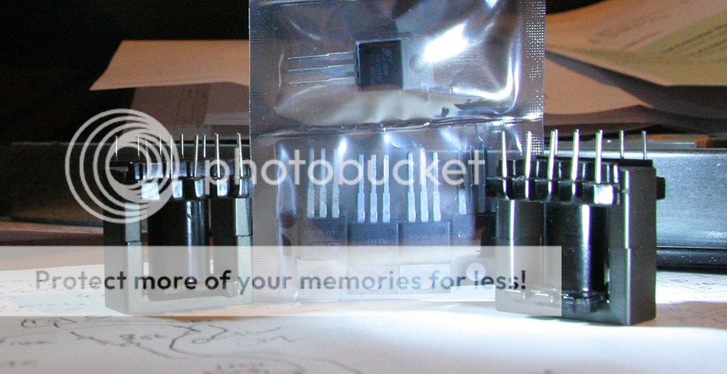
Even stranger, in the surplus section of the same store, some months previously there were small plastic bags of little tan components that looked very much like 1/4 watt resistors. Same size, same shape, same axial wire leads. But the bag was marked "3.3 uF". Nobody in the store knew the voltage rating, but they were cheap and interesting, so I bought a bag.
These are some sort of capacitor - but I've never seen this much capacitance in that small, cylindrical, form-factor. Under a magnifying lens there is a "+" on one end, and I think I also see "30V".
Are they electrolytics? I've never seen an electrolytic cap with wire leads this small before. And these look like moulded plastic, not an aluminium can full of liquid electrolyte. 😕
Whatever they are, these seem to work well as full-bandwidth cathode bypass caps for 12AX7s and so on.
Caps the size of (low-wattage) resistors with microfarad capacities - who saw that coming? I didn't!
-Gnobuddy
Well, that is extremely annoying!...the magic smoke came out on power up.
I have been looking at some of those on Amazon. Some come with specifications such as "reverse polarity protection: Better to not reverse the polarity". Indeed!
In the late 1990s I worked for an audio electronics company. Someone decided that (line powered) switch-mode power supplies would be a good way to go for upcoming products. That was fairly forward-thinking at the time, as SMPS were mostly found only in computers back then.
So they hired a new guy, an engineer who had some previous SMPS design experience. Another engineer was assigned to work with him. These two worked together in the power electronics room over on the far side of the engineering floor. The middle of the floor was the usual cubicle-ville.
Over the next few months, more than once the engineering floor was shaken by a surprisingly loud explosion. It would be followed by the unpleasant stink of freshly fried electronics, and then you would see one or two slightly dazed engineers wandering around, shaking their heads to try to stop the ringing in their ears. The cubicles would be full of startled people standing up, peering around, some clutching at their hearts, and many looking more than a little rattled.
Eventually the power supplies stopped exploding. A new product - a biamplified loudspeaker - was released using one. Unfortunately, after a few months, they began to fail in rather large numbers. One of the electrolytic caps in the SMPS was slowly cooking to death because it was mounted too close to other hot components. Once that cap lost enough of its capacitance, the SMPS would stop working, or worse, pulse on and off several times a second as it attempted to re-start oscillation.
SMPS design seems very different from most types of electronic design. There is art to it as well as science, and these things seem to be balanced on a razors edge all the time. Considering you're constantly switching dozens or hundreds of watts into a tiny inductor with essentially zero series resistance, and hoping to switch it off in time before things explode, I guess that's not too surprising!
But the low-voltage, low-power ones seem rock solid most of the time now, some eighteen years later. I am totally sold on SMPS for heater power, because these low-voltage units are everywhere now, they're cheap, and AC heater power never made sense to me - running an amp or more of noisy AC right next to a millivolt-sensitivity preamp? Really?
It seems 48V is as high as the widely available commercial SMPS go, though. I understand you avoid a slew of safety requirements if you stay under 50V.
Perhaps that's why the higher voltage SMPS are still prone to be unreliable. They are not yet being manufactured by the millions and widely used in consumer equipment.
I know there are exceptions - automotive HID headlamps, for one, which can use kilovolts under certain operating conditions. But those power supplies are not exactly cheap, and the voltage levels are lethal.
-Gnobuddy
I am also pondering a rather more complicated project - an Arduino-controlled swept sine frequency response setup. The Arduino has inadequate speed to synthesize good audio waveforms
STOP, do not pass GO.....go directly to this place and buy a TEENSY 3.2 for $19.80. It has a 72 MHz ARM cortex that is overclockable to 96 MHz or more. It uses the Arduino sketch compiler with an added "TeensyDuino" library.
https://www.pjrc.com/store/teensy32.html
Then go here and get the 44/16 audio shield for $14.25.....not quite good enough for clean 10 KHz square waves, but....
https://www.pjrc.com/store/teensy3_audio.html
Then go here and check out FREE audio library, built into Teensyduino. It lets you play 16 bit stereo WAV files, and has all sorts of tricks up its sleeve, including FFT....enough to build several awesome stomp boxes, or even a complete music synthesizer!
https://www.pjrc.com/teensy/td_libs_Audio.html
I saw this guys synth demo, and at first thought it was fake.....after tinkering for just over a week, I have my own synth running. It still needs some work, but I have four 1 Volt/Octave VCO's, two mixers, a VCF, and an ADSR all running simultaneously inside a single Teensy......It will be posted here eventually. I have a degree in computer engineering, but I haven't written a single line of code in about 5 years.....I'm still in the head scratching, keyboard smashing phase right now.
https://www.youtube.com/watch?v=CXX8q1qiL8E
but I've never seen this much capacitance in that small, cylindrical, form-factor.
You can get 10uF 16V ceramic chip caps in 0805, and 3.3uF in 0603. I have seen tiny molded glass cylindrical devices with a chip cap inside in modern military surplus. You can buy tiny 10uF leaded ceramic caps from Mouser. I'm using these in a consulting project that I'm building:
FK24X5R1C106K TDK | Mouser
I use a voltage doubler for about 140V B+ for small-signal pentodes
Amp 1.5 shown in post #1625 runs on about 165 volts from a Triad N-68X. It makes 4 watts clean and about 5 watts set on metal shred. Sounds cool too when cranked. It will make almost 3 watts on 140 volts, which it where these tubes are supposed to run.....but I like the sound better on 165.
They are not yet being manufactured by the millions and widely used in consumer equipment.
Actually, they are.....the PFC circuit in many PC power supplies takes line voltage and makes about 400 volts DC which feeds the low voltage SMPS....BUT it is NOT isolated from the line so as is the circuit can not be used.....it can be stuck on the output of a Triad N-68X.
I think that axial leaded component is a tantalum cap. I don't like them because they fail at the slightest exceeding of their specs and fail closed - which is not good in most places you need a cap.
The 10uF, 16V caps George linked to are listed as multi-layer ceramic, made by TDK.
I remember seeing those 10uF ceramic leaded caps at Mouser the last time I placed an order, many months ago. I thought I had actually ordered a few of them, for use as cathode bypass caps. But a week or so ago I rooted through my parts box(es) looking for small value caps, and I didn't see any 10 uF ceramics. I guess I never did order them.
I was a wee bit worried about the possibility of exceeding 16V across the cathode resistor during turn-on/ turn-off/ extreme overdrive. But I just realized that running on 300V, with a 100k anode resistor and 1.5k cathode resistor, worst case, with anode directly shorted to cathode, there will only be 4.4 volts across the 1.5k resistor. I guess it's probably safe to use a 16-volt rated cap there.
George, thank you very much for that extremely informative post! Lots to ponder there.
I'm still pondering the "mostly software" vs "mostly analog hardware, with just enough digital and software to run it" approaches. I know which way would make more sense if this was a mass-production commercial product - but, for a one-off, for a person with my relative strengths and weaknesses, the latter approach may be better. I haven't done much coding for microcontrollers, which is one reason I was thinking about the Arduino, with its large community and relative ease of use. I haven't done much coding that interacts with hardware, either.
-Gnobuddy
If it's got a + on one end, it's not ceramic or film, they're non-directional. Tants are polarized and solid, so that's my best bet. I've seen some like that before.
Perhaps we are somehow looking at two different cap types on Mouser? 😕
Here is the (Mouser-provided) link to a PDF datasheet for the caps George and I are talking about: http://www.mouser.com/ds/2/400/eadmlcc_conventional_fk_en-844010.pdf
The datasheet is 23 pages long(!) and I didn't read every word, but it starts out with a description which includes the following text:
[special="High capacitance has been achieved through improvements in the thinning process of ceramic dielectric layers and multi-layer lamination technology..."]%[/special]
No mention of tantalum or electrolytic, only of a layered ceramic dielectric. I did not see any mention of the caps being polarised, either.
On the other hand, those mysterious axial, tan-coloured, moulded, 3.3uF caps I have - the ones that look like 1/4 watt resistors - do seem to have a + on one end. Those may be tantalum, I suppose. Is that what you were referring to?
-Gnobuddy
Attachments

- Home
- Live Sound
- Instruments and Amps
- The Hundred-Buck Amp Challenge