Last night I put a 12W6 in thinking that my 12L6 was a bit to the left in terms of the curve as it broke up pretty early. Theory was to plug in the 12W6 and turn the voltage up in an effort to get some more headroom out of it. Wasn't needed at all. As soon as the 12W6 went in I got nothing but clean tones out of the amp. Now I can't get the damn thing to break up 😛 Also included a POT for the screen resistor for the moment. I'll be playing around with a few different valves and a few different screen resistors so this seemed like the most best option for dialing in what I'm going for. After getting some practice back in and fiddling with things so far, I'm pretty impressed though.
Surprised still that there was such a difference between what are essentially identical valves. the 12L6 is rated up to 200V so am I just pushing it too hard by having that plate right at 200? My P,diss was under rating for both plate and screen, idle current looked good in terms of my operating point, etc. Or is it really just that the valves are more different than I had originally thought....
Surprised still that there was such a difference between what are essentially identical valves. the 12L6 is rated up to 200V so am I just pushing it too hard by having that plate right at 200? My P,diss was under rating for both plate and screen, idle current looked good in terms of my operating point, etc. Or is it really just that the valves are more different than I had originally thought....
Had a sleeve of NOS tubes from one company. Could not get an amp to do what I wanted till I popped out one tube and put in another. Even the same tubes from the same manufacturer can have different behaviors, sometimes you have a dud. Might be the case with your tubes, only way to know is to try a few of each type.
Surprised still that there was such a difference between what are essentially identical valves. the 12L6 is rated up to 200V so am I just pushing it too hard by having that plate right at 200? My P,diss was under rating for both plate and screen, idle current looked good in terms of my operating point, etc. Or is it really just that the valves are more different than I had originally thought....
To paraphrase the signature of a member of the forum:
"Solid state has limits, tubes have recommendations."
Had a sleeve of NOS tubes from one company. Could not get an amp to do what I wanted till I popped out one tube and put in another. Even the same tubes from the same manufacturer can have different behaviors, sometimes you have a dud. Might be the case with your tubes, only way to know is to try a few of each type.
See and I thought that too, but I've got a couple different brands of each and was swapping in and out, for this exact reason! I do get a consistently better performance out of the 12W6 over the 'L6 at the same voltage and operating points however. Eh, no issue really just was kind of surprised is all.
Also have a 5881, 6v6, and 6l6 that made their way to my doorstep earlier today, I'll have to try the 6v6 in the guitar. Others were for additional experiments but may find their way in as well, even just for curiosities sake.
the 12L6 is rated up to 200V so am I just pushing it too hard by having that plate right at 200?........"Solid state has limits, tubes have recommendations."
Some recommendations are more stern than others. The 12L6 and 12W6 will eat far more than 200 volts on the plate IF you keep the screen grid in the 110 to 125 volt range. These tubes will tend to run away if the screen grid voltage goes beyond 125 with elevated plate voltage.
How much plate voltage????
The 12W6 is the winner here. I have run them in push pull at 400 volts resulting in about 40 watts output before the glow of death begins to appear. 50 watts out is possible for shore periods of time.
Some of the 12L6's that I tried got iffy above 350 volts, and some might have been remarked 12W6's because they stood up to the same 400 volt tests.
I would have no problem using any of them at 300 volts and 20 to 25 watts in a guitar amp. 200 volts, no problem, but keep the screen voltage down.
Only got 8-12W6's and 6-6W6's. Almost not worth bothering to use them in an amp. Mind you I could always wire the 6W6's in series, so 7 tube changes. Maybe worth building with then. Wonder what circuit they might sound good in?
Only got 8-12W6's and 6-6W6's. Almost not worth bothering to use them in an amp. Mind you I could always wire the 6W6's in series, so 7 tube changes. Maybe worth building with then. Wonder what circuit they might sound good in?
I actually quite like them as the output driver in the SE "champ" that I've got. Might try them in p-p as an experiment in the future... Re-wired my LDO's last night on a new board with pots for varying the heater voltage (so could do 12V heaters and 6V ones). The amps damn near dead quiet with them out of the chassis so I'll just have to find a good spot to fit them so lead dress doesn't become an issue.
I'd like to try some as gain amps in triode as I've heard now from multiple folks they work well but then I'd be looking at more glass. Could do 2 for gain stages i guess then plug in another dual mu for the PI. (theres an octal out there that works wonders as a PI with a mid/lo mu but it's escaping me at the moment....you guys know what I'm after 😛)
Very nice! A round of applause for you!Here's the latest iteration of my amp. I went with a fairly traditional design<snip>
I must politely demur about the "traditional design", however - I love the amount of original thinking you're put into so many aspects of your amp.
As one small example, the positioning of the knobs on the flat face - originally intended to be the bottom - of the baking pan chassis. Very clever, and I've never seen anyone do it this way before.
If you don't mind, may I ask a couple of questions? One, could you tell us a little more about the process you used to create your labels? What did you use for the acid-resistant resist, how did you apply the text, what acid did you use for the etching, etc?
I've wire-brushed and etched aluminum panels with lye (sodium hydroxide) in the past, which gets you a passable satin-finish on large areas, but I never found a way to do what you've done with the lettering.
The other question I have relates to the circuit itself. I grok the constant current cathode bias regulators, and I think the zeners are there to act as cathode voltage clamps on peaks. I've used that zener clamp technique myself.
But I can't figure out what D3/D4/C7 (and D7/D8/C12) are doing - could you please explain?
-Gnobuddy
Tube Emulation & EQ
Since I'm new to this thread, I should probably mention that, a couple of years ago, the external circumstances of my life changed dramatically, and I found myself re-starting my adult life.
Suddenly I was living in a new place, in a tiny rental suite, with other people living right above the thin ceiling, and still other people living on the other side of the thin wall.
My nominally 15 watt Princeton Reverb was now essentially useless. Turned down to acceptable volume levels, it sounded as bland and uninspired as any cheap solid-state guitar amp.
With the twin pressures of no income (I was still job-hunting at the time) and the mounting desire for a quiet guitar amp, I decided to start to design and build my own. It had to be inexpensive, and it had to sound good (to me).
I have never had an entirely solid-state guitar amp that I liked the sound of. That meant a valve design.
Even though a guitar amp is judged subjectively, this was still an engineering project to me, so objectivity (not emotion) was going to drive the design as much as possible. That means I was perfectly willing to have solid-state components in the design, provided they did not adversely affect the sound quality, and enhanced the design in some way - better function, lower price, whatever.
It's been a long slow road, but I now have a working prototype, and plan to share some details about the design and build here.
I started by trying to establish "acceptable sound volume" actually meant, once translated into in fairly objective engineering terms.
So, one night, I put together an adjustable speaker attenuator, hooked up an old 12" Jensen speaker I had to a signal generator, and was shocked to find out that I could very audibly hear the test tone with about ten millivolts of drive to the (8 ohm) speaker; that translates to just barely ten *microwatts* of power!
At first I was convinced I had made a calculation error, but a few checks and re-checks convinced me that I hadn't. Ten microwatts is (-50) dBW. Run that into a speaker with, say, 95 dB / watt sensitivity, and you should have (95-50), or 45 dB SPL @ 1 metre.
45 dB SPL is quiet - but very distinctly audible, and in fact, loud enough to be very annoying when you listen to a 1 kHz sine wave test tone for more than a few seconds!
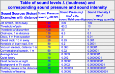
With my initial expectations of "low power" shattered - I did not anticipate microwatts - I went looking for information on subjective descriptions for SPL numbers. I quickly found a number of suitable tables, one of which is attached.
This particular table compares 80 dB SPL to being 5 metres from a busy road. 70 dB SPL is compared to a vacuum cleaner at 1 metre distance. 60 dB is similar to "conversational speech".
One can argue about the exactness of those numbers (How busy a road? How loud a vacuum cleaner?) But they at least provide a starting point.
In other words, I'm pretty sure my neighbours don't want to hear my electric guitar sounding as the "kerbside of a busy road" (80 dB) under any circumstances. They *might* be okay - during the daytime - with my guitar sounding as loud as a vacuum cleaner (70 dB). But at night, that better come down to no louder than "conversational speech", i.e. 60 dB SPL, and maybe even lower, to the 50 dB SPL range, as loud as the "average home".
That gave me initial targets for my guitar amps expected SPL numbers. I would need acceptable guitar tone at a maximum of 60 dB SPL if I expected to use the amp in my apartment at night without annoying the neighbours. During the daytime, that might be increased to a maximum of maybe 80 dB SPL, though 70 dB would be a safer number.
In a later post I will translate these SPL numbers to guitar amp output power numbers. The results shocked me, and perhaps they might surprise you, too!
-Gnobuddy
Since I'm new to this thread, I should probably mention that, a couple of years ago, the external circumstances of my life changed dramatically, and I found myself re-starting my adult life.
Suddenly I was living in a new place, in a tiny rental suite, with other people living right above the thin ceiling, and still other people living on the other side of the thin wall.
My nominally 15 watt Princeton Reverb was now essentially useless. Turned down to acceptable volume levels, it sounded as bland and uninspired as any cheap solid-state guitar amp.
With the twin pressures of no income (I was still job-hunting at the time) and the mounting desire for a quiet guitar amp, I decided to start to design and build my own. It had to be inexpensive, and it had to sound good (to me).
I have never had an entirely solid-state guitar amp that I liked the sound of. That meant a valve design.
Even though a guitar amp is judged subjectively, this was still an engineering project to me, so objectivity (not emotion) was going to drive the design as much as possible. That means I was perfectly willing to have solid-state components in the design, provided they did not adversely affect the sound quality, and enhanced the design in some way - better function, lower price, whatever.
It's been a long slow road, but I now have a working prototype, and plan to share some details about the design and build here.
I started by trying to establish "acceptable sound volume" actually meant, once translated into in fairly objective engineering terms.
So, one night, I put together an adjustable speaker attenuator, hooked up an old 12" Jensen speaker I had to a signal generator, and was shocked to find out that I could very audibly hear the test tone with about ten millivolts of drive to the (8 ohm) speaker; that translates to just barely ten *microwatts* of power!
At first I was convinced I had made a calculation error, but a few checks and re-checks convinced me that I hadn't. Ten microwatts is (-50) dBW. Run that into a speaker with, say, 95 dB / watt sensitivity, and you should have (95-50), or 45 dB SPL @ 1 metre.
45 dB SPL is quiet - but very distinctly audible, and in fact, loud enough to be very annoying when you listen to a 1 kHz sine wave test tone for more than a few seconds!
With my initial expectations of "low power" shattered - I did not anticipate microwatts - I went looking for information on subjective descriptions for SPL numbers. I quickly found a number of suitable tables, one of which is attached.
This particular table compares 80 dB SPL to being 5 metres from a busy road. 70 dB SPL is compared to a vacuum cleaner at 1 metre distance. 60 dB is similar to "conversational speech".
One can argue about the exactness of those numbers (How busy a road? How loud a vacuum cleaner?) But they at least provide a starting point.
In other words, I'm pretty sure my neighbours don't want to hear my electric guitar sounding as the "kerbside of a busy road" (80 dB) under any circumstances. They *might* be okay - during the daytime - with my guitar sounding as loud as a vacuum cleaner (70 dB). But at night, that better come down to no louder than "conversational speech", i.e. 60 dB SPL, and maybe even lower, to the 50 dB SPL range, as loud as the "average home".
That gave me initial targets for my guitar amps expected SPL numbers. I would need acceptable guitar tone at a maximum of 60 dB SPL if I expected to use the amp in my apartment at night without annoying the neighbours. During the daytime, that might be increased to a maximum of maybe 80 dB SPL, though 70 dB would be a safer number.
In a later post I will translate these SPL numbers to guitar amp output power numbers. The results shocked me, and perhaps they might surprise you, too!
-Gnobuddy
Attachments
In my last post, I set initial SPL targets of 60 dB to 80 dB for my guitar amp design, as those seemed likely to be acceptable to the neighbours.
The next step was to translate those into actual guitar amp output power in watts. The translation requires the speaker sensitivity (dB SPL at 1 metre for 1 watt input power), and a few assumptions about the environment (such as, how far your ear will be from the guitar speaker).
Assuming a typical small room, the guitar amp will be within two or three metres of your ears. Assuming a fairly acoustically reflective room, the SPL at your ears won't be much less than the (anechoic) SPL at 1 metre that the speaker specifications list.
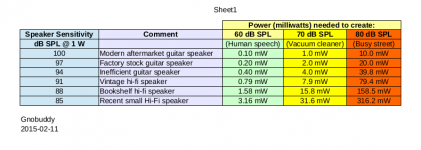
With those assumptions, I put together a little spreadsheet that contained a list of typical speaker sensitivities, and calculated the power in watts needed to drive them to my three target SPL levels of 60 dB, 70 dB, and 80 dB.
Here's a (pdf copy) of the spreadsheet. Using an efficient guitar speaker, we only need a few milliwatts (!) to achieve even the highest of the three SPL numbers.
At the other end of the scale, a quite inefficient contemporary speaker (perhaps designed for a small bookshelf Hi-Fi speaker system) might require as much as one-third of a watt to hit 80 dB SPL - which, I might remind you, your neighbours might find obnoxiously too loud.
Now we know why we hear so many complaints on the Internet about 5 watt amps being far too loud for home use! What we actually need is an output power controllable down to a few milliwatts, and we probably won't need a maximum sustained output power any higher than maybe a hundred milliwatts.
I found that these theoretical estimates seem to apply fairly well to overdriven guitar sounds, which have very little dynamic range, so that the output power from the amp is fairly constant for the entire duration of the notes emitted by the guitar.
Clean guitar sounds are a different story. Guitars emit a big initial transient, followed by a fairly rapid decay. The average SPL is much less than that initial peak. Put another way, to get an average SPL of, say, 70 dB, you need a peak SPL that is much higher. That means you need considerably higher peak power than the figures in my spreadsheet.
In practice, I found that maybe one or two watts RMS was a good maximum power target for *clean* guitar tones. For heavily overdriven tones, the output power needed to be in milliwatts, as the spreadsheet predicts.
-Gnobuddy
The next step was to translate those into actual guitar amp output power in watts. The translation requires the speaker sensitivity (dB SPL at 1 metre for 1 watt input power), and a few assumptions about the environment (such as, how far your ear will be from the guitar speaker).
Assuming a typical small room, the guitar amp will be within two or three metres of your ears. Assuming a fairly acoustically reflective room, the SPL at your ears won't be much less than the (anechoic) SPL at 1 metre that the speaker specifications list.
With those assumptions, I put together a little spreadsheet that contained a list of typical speaker sensitivities, and calculated the power in watts needed to drive them to my three target SPL levels of 60 dB, 70 dB, and 80 dB.
Here's a (pdf copy) of the spreadsheet. Using an efficient guitar speaker, we only need a few milliwatts (!) to achieve even the highest of the three SPL numbers.
At the other end of the scale, a quite inefficient contemporary speaker (perhaps designed for a small bookshelf Hi-Fi speaker system) might require as much as one-third of a watt to hit 80 dB SPL - which, I might remind you, your neighbours might find obnoxiously too loud.
Now we know why we hear so many complaints on the Internet about 5 watt amps being far too loud for home use! What we actually need is an output power controllable down to a few milliwatts, and we probably won't need a maximum sustained output power any higher than maybe a hundred milliwatts.
I found that these theoretical estimates seem to apply fairly well to overdriven guitar sounds, which have very little dynamic range, so that the output power from the amp is fairly constant for the entire duration of the notes emitted by the guitar.
Clean guitar sounds are a different story. Guitars emit a big initial transient, followed by a fairly rapid decay. The average SPL is much less than that initial peak. Put another way, to get an average SPL of, say, 70 dB, you need a peak SPL that is much higher. That means you need considerably higher peak power than the figures in my spreadsheet.
In practice, I found that maybe one or two watts RMS was a good maximum power target for *clean* guitar tones. For heavily overdriven tones, the output power needed to be in milliwatts, as the spreadsheet predicts.
-Gnobuddy
Attachments
Gnobuddy:
My first iteration of my amp had a L-pad on the output to control the output volume. It allowed overdrive and transformer saturation for tone but still allowed you to control the overall volume independently. Speaker efficiency has always been the most critical part of volume and one of the most overlooked.
To make the lettering, here's what I did:
Sand the surface to remove the anodized layer (I didn't do this, I really should have). I purchased some vinyl lettering (I used https://doityourselflettering.com ), choose the "weed and tape yourself" option. This means that it comes cut but still has the surrounding vinyl. Put a piece of masking tape on the vinyl, remove the adhesive backing, and then remove the LETTERS, not the surrounding vinyl, creating a kind of stencil. Put the stencil where you want it. Then cover the rest of the panel in electrical tape for protection. I use an etchant of equal parts muriatic (hydrochloric) acid and hydrogen peroxide. I brush it on with an acid brush and wipe up any excess to keep it from bleeding between the tape gaps. It should bubble vigorously. Needless to say, do this a well ventilated area. When it stops, wipe off the old and add more etchant. When you've etched down a few mil, wipe off all the etchant and rinse thoroughly. Remove all the tape. I then use a cheap small brush with black appliance epoxy to fill in the etched letters and a Q tip moistened with mineral spirits to clean up any mistakes.
The cathode biasing was unabashedly taken from Broskie here: Cathode Bias with a Counstant Current Source
As Broskie says:
"Okay, why is the zener there? The zener diode will put the hard breaks on the cathodes climbing too high in voltage due to rectification effects that result from overdriving the triodes. Just pick a zener that will break at some voltage beyond what you ever expect to find a triode biasing to at the desired idle current. In fact, we could just use a zener and the constant-current source, but it results in sharp transitions in the waveform—never a sonically good idea. The more complex circuit allows a smoother transition."
Last edited:
I have an L-pad on my prototype amp, too. Before that, I was using one with my 15-watt Princeton Reverb. It didn't work too well in that situation - you end up with the L-pad set to virtually it's zero position by the time the overdriven volume is "house-friendly". I ended up using a fixed -6 dB (quarter power) attenuator in front of the L-pad; combined, they worked fairly well.My first iteration of my amp had a L-pad on the output to control the output volume.
A single L-pad does work pretty well on my (roughly 2W max) prototype amp, though, and for me, it's an essential part of the recipe for achieving overdriven sound at reasonable SPL levels.
I wish you lived next door to me, I might have made much faster progress with my amp project if you had!Speaker efficiency has always been the most critical part of volume and one of the most overlooked.
I certainly overlooked the degree to which speaker efficiency mattered in a guitar amp until I realized that for low-power use, I didn't have to use a guitar-specific driver. Suddenly I could choose speakers rated anywhere from around 82 dB/W/m all the way up to around 102 dB/W/m. That is a hundred-to-one ratio terms of power needed for a given SPL!
Thank you very much for sharing your method. I'm filing that away for possible future use one day!To make the lettering, here's what I did:
<snip>
Thanks also for the link to Broskie's write-up. It's rather funny, Broskie is throwing everything he can at an extremely non-linear circuit block in the attempt to make it a bit more linear (for Hi-Fi purposes). For guitar-amp purposes, I found myself doing somewhat the opposite, designing to maintain the nonlinear nature of valves as much as possible.
I used a push-pull output stage too, and to my ears, the biggest problem (by far) was blocking distortion when overdriving the circuit. The traditional remedies for blocking distortion (smaller coupling caps, increased output valve grid stopper resistance values) did not solve the problem to my satisfaction. A little time with LTSpice confirmed that those remedies didn't solve the underlying problem, they only changed the related time-constants.
-Gnobuddy
Sorry I've been silent so long, work was crazy busy for a while.
For my amp project, I spent quite a lot of time trying to re-think the traditional ways of physically constructing the actual circuitry. Tag-strips and turret boards were perfectly good choices in 1955, but today these are specialty items. I wanted to find a replacement that I didn't have to mail-order.
Also, I knew nothing about making a good guitar amp when I started, which meant I would have to modify, rip out, and re-do parts of the circuit as I learned what worked, and what didn't. I needed a flexible construction method that could easily accommodate changes - that means PCB construction was ruled out.
I don't enjoy doing the same complex and time-consuming task twice, so if possible, I wanted a prototyping method that would also serve as the final construction method - no need to build the whole thing over again.
Also, I wanted a nice tight layout - no long dangling wires everywhere, to pick up noise and cause RF instability. And I like the physical layout to at least somewhat mirror the schematic: inputs on one end, outputs on the other, positive supply rail along one edge, ground along the other, et cetera.
After much head-scratching, I came up with something that met all these requirements. The circuits are built on 3/8" thick, 4" wide x 12" long rectangles of plywood from Michaels (arts and crafts store) as the substrate.
Chassis-mount valve sockets were mounted in through-holes cut in the plywood. Physically, plywood of this thickness and size is very sturdy. It can easily carry the weight of small transformers and valves, and cope with valve insertion/removal forces.
The small components (resistors, caps, etc) are mounted flat on the underside of the plywood. They are soldered to tie-points which are #2 brass wood-screws, 3/8" long, which I found at Lowes hardware. The screws are short enough not to protrude through the other side of the ply, particularly because I leave the head and about 1/8" of the shaft sticking out of the wood on the underside.
Big components - large filter caps, transformers, valves - go on the top of the plywood, with through-holes for leads as necessary. Just keep temperature-sensitive components well away from the valve bottles. (Transformers mount with through-bolts, with lock-washers and nuts on the other side of the ply. We don't want tiny wood-screws to pull out and allow a live transformer to flail around. 😱 )
Obviously, it is really easy to add new tie-points (screws!) as necessary, if the circuitry evolves. I drill a pilot hole for each screw, using a small drill bit and a pin vise held between my fingers. That ensures no splintering or flaking of the wood.
I am very happy with how this construction method turned out. Easy availability, good layout, short leads, good durability. To me, this method incorporates some of the best aspects of both PCB and turret-board construction, and - for home-constructed one-off valve designs - improves on both.
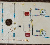
Attached is a picture of the underside of my power amp board, at an early point during the construction. You can see the sockets for the output valves, and some of the passive components around them. You can also see the bare copper wire rails for small-signal ground and B+.
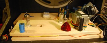
The second picture shows the top of the power amp board, during early testing. (It was plagued with blocking distortion at this point in the design process.) The Fender guitar pick is for scale. These are little valves!
If you recognize any of the valves in the photos, please don't mention the part number here. We don't want that mysterious Hong Kong outfit that George told us about, buying the entire supply, and most likely, crushing them into powder. Once these are gone, they're gone for good - none of these valves is in current production.
You may have noticed three semiconductor devices in one of the photos - a three-lead device in a T0-92 package, and a pair of series-back-to-back zener diodes.
Back in 2014 I came to the conclusion that using a valve in a cathodyne phase-splitter was a total waste of a good valve; with 100% local negative feedback, a cathodyne has too little distortion to be audible when operated below clipping. That means, when not overdriven, a valve cathodyne is audibly transparent, "solid state clean", with no "valvey" sound to contribute to the amp. And if you do overdrive it, it has a tendency to make some very nasty noises, unless you carefully design them away.
I remember that Tubelab George has expressed a similar opinion somewhere in this very long thread.
So, the little black plastic object in the attached photo is a TO-92 MOSFET, a Supertex LND-150 N-channel, depletion-mode device that is well known on this forum. It's wired up as a "source-o-dyne" phase splitter.
It's essentially the same as a cathodyne, except for the biasing method. MOSFET's have far too much tolerance in their electrical parameters to be reliably "self biased" like a valve. So the gate is biased to one-quarter of B+ using a voltage divider.
IMO, a mosfet makes a much better phase splitter than a valve-based cathodyne. It is 100% audibly transparent and contributes nothing to the sound of the amp, just like the cathodyne; it can output a much bigger signal than a triode running off the same B+; no heater elevation voltage is required; and it has none of the nasties that can afflict a true valve-based cathodyne.
In addition, of course, it's small, light, cheap, and requires no heater power.
-Gnobuddy
For my amp project, I spent quite a lot of time trying to re-think the traditional ways of physically constructing the actual circuitry. Tag-strips and turret boards were perfectly good choices in 1955, but today these are specialty items. I wanted to find a replacement that I didn't have to mail-order.
Also, I knew nothing about making a good guitar amp when I started, which meant I would have to modify, rip out, and re-do parts of the circuit as I learned what worked, and what didn't. I needed a flexible construction method that could easily accommodate changes - that means PCB construction was ruled out.
I don't enjoy doing the same complex and time-consuming task twice, so if possible, I wanted a prototyping method that would also serve as the final construction method - no need to build the whole thing over again.
Also, I wanted a nice tight layout - no long dangling wires everywhere, to pick up noise and cause RF instability. And I like the physical layout to at least somewhat mirror the schematic: inputs on one end, outputs on the other, positive supply rail along one edge, ground along the other, et cetera.
After much head-scratching, I came up with something that met all these requirements. The circuits are built on 3/8" thick, 4" wide x 12" long rectangles of plywood from Michaels (arts and crafts store) as the substrate.
Chassis-mount valve sockets were mounted in through-holes cut in the plywood. Physically, plywood of this thickness and size is very sturdy. It can easily carry the weight of small transformers and valves, and cope with valve insertion/removal forces.
The small components (resistors, caps, etc) are mounted flat on the underside of the plywood. They are soldered to tie-points which are #2 brass wood-screws, 3/8" long, which I found at Lowes hardware. The screws are short enough not to protrude through the other side of the ply, particularly because I leave the head and about 1/8" of the shaft sticking out of the wood on the underside.
Big components - large filter caps, transformers, valves - go on the top of the plywood, with through-holes for leads as necessary. Just keep temperature-sensitive components well away from the valve bottles. (Transformers mount with through-bolts, with lock-washers and nuts on the other side of the ply. We don't want tiny wood-screws to pull out and allow a live transformer to flail around. 😱 )
Obviously, it is really easy to add new tie-points (screws!) as necessary, if the circuitry evolves. I drill a pilot hole for each screw, using a small drill bit and a pin vise held between my fingers. That ensures no splintering or flaking of the wood.
I am very happy with how this construction method turned out. Easy availability, good layout, short leads, good durability. To me, this method incorporates some of the best aspects of both PCB and turret-board construction, and - for home-constructed one-off valve designs - improves on both.
Attached is a picture of the underside of my power amp board, at an early point during the construction. You can see the sockets for the output valves, and some of the passive components around them. You can also see the bare copper wire rails for small-signal ground and B+.
The second picture shows the top of the power amp board, during early testing. (It was plagued with blocking distortion at this point in the design process.) The Fender guitar pick is for scale. These are little valves!
If you recognize any of the valves in the photos, please don't mention the part number here. We don't want that mysterious Hong Kong outfit that George told us about, buying the entire supply, and most likely, crushing them into powder. Once these are gone, they're gone for good - none of these valves is in current production.
You may have noticed three semiconductor devices in one of the photos - a three-lead device in a T0-92 package, and a pair of series-back-to-back zener diodes.
Back in 2014 I came to the conclusion that using a valve in a cathodyne phase-splitter was a total waste of a good valve; with 100% local negative feedback, a cathodyne has too little distortion to be audible when operated below clipping. That means, when not overdriven, a valve cathodyne is audibly transparent, "solid state clean", with no "valvey" sound to contribute to the amp. And if you do overdrive it, it has a tendency to make some very nasty noises, unless you carefully design them away.
I remember that Tubelab George has expressed a similar opinion somewhere in this very long thread.
So, the little black plastic object in the attached photo is a TO-92 MOSFET, a Supertex LND-150 N-channel, depletion-mode device that is well known on this forum. It's wired up as a "source-o-dyne" phase splitter.
It's essentially the same as a cathodyne, except for the biasing method. MOSFET's have far too much tolerance in their electrical parameters to be reliably "self biased" like a valve. So the gate is biased to one-quarter of B+ using a voltage divider.
IMO, a mosfet makes a much better phase splitter than a valve-based cathodyne. It is 100% audibly transparent and contributes nothing to the sound of the amp, just like the cathodyne; it can output a much bigger signal than a triode running off the same B+; no heater elevation voltage is required; and it has none of the nasties that can afflict a true valve-based cathodyne.
In addition, of course, it's small, light, cheap, and requires no heater power.
-Gnobuddy
Attachments
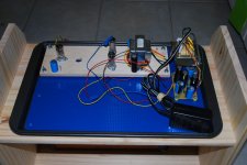
The other half of the "plywood and brass screws" circuitry is a metal chassis made from a dollar-store cookie baking tray.
The construction is inverted compared to the traditional way valve circuits are built, i.e. the chassis is on the bottom, with the circuit boards (carrying the valves) mounted on top of it with machine screws, nuts, and standoffs.
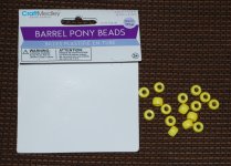
The standoffs are "pony barrel beads" from, of course, the dollar store.
There is an insulating sheet between the metal chassis and the underside of the circuit boards; we don't want brass screws carrying 280 volts to short out to the grounded metal chassis! The insulating sheet is another dollar-store item, this time a plastic kitchen cutting board.
This construction method reduces metalworking to a minimum. There are no complicated holes to cut in the metal chassis - no rectangular transformer openings, no lopsided hexagons for IEC inlets, etc. The chassis tray only needs small holes drilled in it for the mounting bolts. That is easily done with a hand-held electric drill.
-Gnobuddy
The construction is inverted compared to the traditional way valve circuits are built, i.e. the chassis is on the bottom, with the circuit boards (carrying the valves) mounted on top of it with machine screws, nuts, and standoffs.
The standoffs are "pony barrel beads" from, of course, the dollar store.
There is an insulating sheet between the metal chassis and the underside of the circuit boards; we don't want brass screws carrying 280 volts to short out to the grounded metal chassis! The insulating sheet is another dollar-store item, this time a plastic kitchen cutting board.
This construction method reduces metalworking to a minimum. There are no complicated holes to cut in the metal chassis - no rectangular transformer openings, no lopsided hexagons for IEC inlets, etc. The chassis tray only needs small holes drilled in it for the mounting bolts. That is easily done with a hand-held electric drill.
-Gnobuddy
Attachments


Thank you! I was beginning to wonder if I was the only one in the room! 🙂Nice lateral thinking 😉
I know this thread is now five years old, but I am still enjoying each new post from everyone who is keeping the thread alive!
-Gnobuddy
I was beginning to wonder if I was the only one in the room!
Some of us only visit the room every few days....The new version of Amp 1.5 that I made is still waiting for a proper chassis and cabinet. That will happen when the weather is good enough to drag the table saw outside.
There is an "kitchen sink amp" in the works. It's different that I started with the cabinet, purchased cheap at a Goodwill store. I'm currently in the process of stuffing everything but the kitchen sink inside the box. It will be like nothing seen here before, but definitely doesn't fit this challenge. It will have a guitar input, and speaker outputs, so it can be called a guitar amp, among other things.
Thank you! I was beginning to wonder if I was the only one in the room! 🙂
-Gnobuddy
Nope. Working on my pp EL91 with ECF80 preamp using 100v line trafo for OPT, all powered by a 12vac wall wart and cased in a trade-aid jewellery box 🙂
And VVR'd with a 25c Thai IRF820 off eBay.
Last edited:
Been sick for a few weeks. Hopefully soone I will be working on a FET preamp to put in front of a 5W Class A MOSFET amp. Then compare it to a SE Champ type amp. Other projects are a 40W Class D switching amp (TPA3118) as a lightweight backup amp. Going where others with more sense fear to tread, plan to blow up a bunch of semiconductors while trying to make a switching power supply for a 20W tube amp. Trying to get my shop back together and make some tooling to make acoustic guitars.
Probably could do a cheap and dirty pentode front ended practice amp that I had planned at around AMP Ver. 6.0 or so. Sometimes you need a diversion.
Probably could do a cheap and dirty pentode front ended practice amp that I had planned at around AMP Ver. 6.0 or so. Sometimes you need a diversion.
Yeah, but you've been at it since 2011, so every few days in 2016 is pretty impressive!Some of us only visit the room every few days....
I've enjoyed your previous contributions here, and look forward to seeing your future posts.
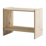
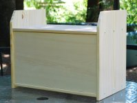
Speaking of guitar cabs, a while ago I stumbled across one solution to to the DIY guitar cab problem. IKEA makes a little solid-pine night stand called the RAST, which sells for $20 in Canada and $15 in the USA. ( RAST Nightstand - IKEA ).
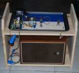
Flip a RAST upside down and add a front and/or rear panel, and it makes an excellent guitar combo//speaker cab. For those of us without access to a table saw and/or the skills to use one, this makes constructing a cab a whole lot easier. 🙂
It will fit up to a 10" speaker in stock form; one shelf can easily be moved over to fit a 12" if desired, all that's required is drilling six screw holes. My tip for this is to use the existing holes in the second end panel as a jig to drill the new holes in the first end panel - that way you get perfect spacing and alignment automatically.
The pics below show part of the tale of my RAST turned combo guitar cab. One intermediate stage in the process used a rather sorry-looking $4 thrift store JVC speaker lying inside the RAST, while I waited for the speaker I actually wanted to arrive in the mail.
-Gnobuddy
Attachments
- Home
- Live Sound
- Instruments and Amps
- The Hundred-Buck Amp Challenge