Re: PSUs per Channel; Cap values; Cap ratings; Snubber Values
Two channels.
You can use them per channel, if you want.
Yes.
Parallel two big caps.
Be a man and make the latest CRCCS PSU.😀
GeorgeBoles said:1. Embarassing question: are all the unregulated PSUs in this thread for one channel? Are the later ones (with higher capacitance for two channels?
Two channels.
You can use them per channel, if you want.
GeorgeBoles said:b) Should these be OK with your standard snubber values?
Yes.
Parallel two big caps.
Be a man and make the latest CRCCS PSU.😀
Be a man and make the latest CRCCS PSU. From Carlos
That is the plan, good man. 😎
Ordering parts today.
At times like this, being in a regional centre in Oz makes it all quite difficult. I even have to get 2oz PCB blank mailed in, and even that doesn't come from one of our national electronics components suppliers: I have to buy it from a PCB manufacturer ... more Post and Handling. Until I discovered those cheap capacitors, it was scadoodles cheaper to get the order sent across from Digikey USA! (I have to re-check the sums now. 🙂 ) Speaker drivers are cheaper by far from Madisound New York than here in Australia, but admittedly I have not yet pushed for huge discounts from our local suppliers to see if they can come to the party for my Orions-to-be.
Regards,
George.
George,
Where are you getting those caps for only $1 USD? Also where are you getting the 2oz PCB's from?
Thanks.
Where are you getting those caps for only $1 USD? Also where are you getting the 2oz PCB's from?
Thanks.
Hey carlosfm i got a question for you,
I just recently decided to jump into this snubberized thingy.
Would your MkIV PSU work with any amp or is it just with the LM chips?
I was thinking that I would try it with the UCD(400 or 700) amp when I get around to buying them.
Thanks
Lawrence
I just recently decided to jump into this snubberized thingy.
Would your MkIV PSU work with any amp or is it just with the LM chips?
I was thinking that I would try it with the UCD(400 or 700) amp when I get around to buying them.
Thanks
Lawrence
It should work.
I have french reports of very good results, and that was with the original snubberized PSU.
Oui, ça marche.😉
LM chips are not such an exquisite specimen.
What's the amplifier that doesn't like a low impedance PSU?
I have french reports of very good results, and that was with the original snubberized PSU.
Oui, ça marche.😉
LM chips are not such an exquisite specimen.
What's the amplifier that doesn't like a low impedance PSU?
Mangrove Jack,
1. Caps have all gone 🙁 .
2. PCB material from becman.com
"BEC Manufacturing"
$30 for 18" * 12" 2oz double sided board. Post approx $5.
Regards,
George.
1. Caps have all gone 🙁 .
2. PCB material from becman.com
"BEC Manufacturing"
$30 for 18" * 12" 2oz double sided board. Post approx $5.
Regards,
George.
1. Caps have all gone .
Don't be too disappointed George. I have bought two lots of cheap caps in the past (Ebay) and neither were very good. Caps have a shelf life and I suspect the ones that come up for grabs at 'bargain' prices are may be not such a bargain as we would like them to be!

GeorgeBoles said:1. Caps have all gone 🙁 .
Next time you know: first you order them, then you post on diyaudio.com😀
'Tis always the way.
XELB your PSU whilst valid has one serious flaw - the cap cascade will be acting as one massive cap to the rectifiers, so the draw current pulses will be extremely short and massive in value... producing a ton more hf noise...
If it were mine, I'd put a smallish cap immediately after the bridge, and seperate it from the main charge store either by an inductor (my preference) or a resistor - the charge drain resistor from rail to ground is also a good idea. This will help smooth the load on the rectifier, reducing the source of noise.
This is never a bad thing.
Just some thoughts...
Have fun
Owen
Ps. you'll see most of this in the carlos schematic.. 🙂
Me too, me too!
Me too, me too, dear Carlos!
About one year ago, I experimented with brute force: a breadboard LM3875 amp with big caps (some experiments with more than 40mF overall). In the beginning, it was a noninverting, in the meantime a t-net inverting circuit without input poti, just powerstage.
This configuration was still available (working at my PC). Very simple setup (stereo):
- 4 x 10000uF Jamicon
- 4 x 2200uf Philips
- 4 x 1uF MKT*
- 4 x 0.1uF MKT*
and nearby the chips no electrolytics, just 4 x 0.1uF MKT.
I just replaced the caps marked with an asteriks by four snubbers, 1R/0.1uF.
As you can imagine: the result is really great, a really big difference, despite of the missing caps nearby the chips.
Of course, I will insert some.
Carlos: do you "snubberize" the 0.1uF caps nearby the pins of the chip?
Franz
Attachments
Franz G said:Me too, me too, dear Carlos!
...
As you can imagine: the result is really great, a really big difference...
Yes, I can imagine, Franz.😀
Franz G said:...despite of the missing caps nearby the chips.
Of course, I will insert some.
Carlos: do you "snubberize" the 0.1uF caps nearby the pins of the chip?
Franz
If I understand correctly from your pic, you have the big caps near the chips.
You should snubberize the last big caps, and they should be as near as possible to the chips (which is not so clear), even if it means removing the 1uf MKT caps.
Oh, you may want to try the values of the latest PSU.
0.47R + 1.5nf.
XELB,
Yup a snubber on the diodes will help tame RF hash - my point of view is dont create much in the first place....
Different perspective
Owen
Yup a snubber on the diodes will help tame RF hash - my point of view is dont create much in the first place....
Different perspective
Owen
If I understand correctly from your pic, you have the big caps near the chips.
You should snubberize the last big caps, and they should be as near as possible to the chips (which is not so clear), even if it means removing the 1uf MKT caps.
Oh, you may want to try the values of the latest PSU.
0.47R + 1.5nf.
__________________
Carlos Filipe.
You understood the situation correctly:
The big caps are nearby the chips, but the 1uF MKT is already removed.
Followed by the snubbers and directly at the pins 0.1uF MKT's.
Yesterday evening, I attached some Silmic cap's 220uF just 2mm before the pins, what messed up the sound completely.
I will try your latest snubber values soon.
While experimenting, I realized that this experimental pcb I made a year before is very usefull for a very simple and small snubberized stereoamp. Just add 8 diodes in front of the circuit, the caps are all sitting very nearby the chip.
Regards
Franz
Attachments
carlosfm said:Oh, you may want to try the values of the latest PSU.
0.47R + 1.5nf.
 Seems very sensible to add these parts....
Franz, I see no problem if you add your 1 uF but then again the main reason for adding 100 nF or something is for stability reasons mainly. I'll guess a good pcb (or circuit solutuion) plus at least 47-100 nF plus 100 uF or so very near the IC pins is a good rule (accordning to trhe datasheet), with or without snubbers and if you should snubberize seriously you should not have any high-Q cap (polyester, polyprop, ceramics) unsnubbed. All "good caps should have a small resistance.
Franz G said:The big caps are nearby the chips, but the 1uF MKT is already removed.
Followed by the snubbers and directly at the pins 0.1uF MKT's.
Guden tag, Franz.
The idea was to remove the 1uf MKT caps and get the 2,200uf caps near(er) to the chips.
I don't know if that's possible, but you can make new holes on the PCB to relocate the 2,200uf caps.
You don't need smaller electros there.
owen said:XELB,
Yup a snubber on the diodes will help tame RF hash - my point of view is dont create much in the first place....
Different perspective
Owen
Due to different prespectives we have evolution 😉
I have no problem in try, if it doesn't work.... no problem 😎
I was out of the country and I am with tons of work.

when I have a free time I will finish my LM amp and test the two PSU.
I will have no problem in make a report 🙂
> Yesterday evening, I attached some Silmic cap's 220uF just
> 2mm before the pins, what messed up the sound completely.
I had the same experience with 100uF right at the IC pins.
(The sound was much worser, hazy, zzrzfrzshzsss........ 🙂
With a bigger value like 2200uF the effect should be different ?
Snubber (1R+100nF) is only at the main PS block, the wire length
to the IC is ~ 2".
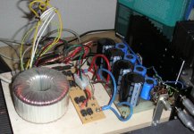
I finally got around to building my gainclone and followed a lot of the suggestions from this thread on power supply design. Nothing too original here but I thought I'd share another example.
Power transformer was a 225VA Plitron 18V + 18v that I picked up relatively cheap on the surplus market a few years back. I built the standard NIGC based on the BrianGT kit and then added the snubber power supply. A lot of this was based on what parts I had available in my work room so it does take off from the original suggestions. After the rectifiers I use 4700uf - 2ohm resistor - 20000uf (2 10Kuf caps).
Across the 20Kuf caps I placed 0.22uf polypro caps (wima) and a 0.5ohm/1.5nf snubber. Across the pins of the LM3875 chip I placed a 0.47uf cap. The BrianGT boards had 1500uf caps and I placed 0.1uf caps across these and 0.5ohm/47nf snubbers.
I added all the bypass caps in stages and can report that the sound kept getting better as I added every component and only the full complement gave what I consider excellent sound. I experimented with output resistors (0.22ohms) or output inductors and preferred the sound without either. Right now I'd say that this is a truly excellent amp and compares very favorably to some very good amps. I took it over to a friends house and listened to some Fertin full range drivers and we felt it stood up very well to some nice single ended tube amps.
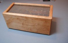
I built the amp in a homebrew box out of solid 3/4" maple and used a block of copper as the heat sink and a small piece of copper clad PC board as a shield between the transformer and the amp components. Dimensions of the amp are 12.5" (wide) x 6.5" (deep) x 6" (tall).
---Gary
Power transformer was a 225VA Plitron 18V + 18v that I picked up relatively cheap on the surplus market a few years back. I built the standard NIGC based on the BrianGT kit and then added the snubber power supply. A lot of this was based on what parts I had available in my work room so it does take off from the original suggestions. After the rectifiers I use 4700uf - 2ohm resistor - 20000uf (2 10Kuf caps).
Across the 20Kuf caps I placed 0.22uf polypro caps (wima) and a 0.5ohm/1.5nf snubber. Across the pins of the LM3875 chip I placed a 0.47uf cap. The BrianGT boards had 1500uf caps and I placed 0.1uf caps across these and 0.5ohm/47nf snubbers.
I added all the bypass caps in stages and can report that the sound kept getting better as I added every component and only the full complement gave what I consider excellent sound. I experimented with output resistors (0.22ohms) or output inductors and preferred the sound without either. Right now I'd say that this is a truly excellent amp and compares very favorably to some very good amps. I took it over to a friends house and listened to some Fertin full range drivers and we felt it stood up very well to some nice single ended tube amps.
I built the amp in a homebrew box out of solid 3/4" maple and used a block of copper as the heat sink and a small piece of copper clad PC board as a shield between the transformer and the amp components. Dimensions of the amp are 12.5" (wide) x 6.5" (deep) x 6" (tall).
---Gary
Attachments
- Status
- Not open for further replies.
- Home
- Amplifiers
- Chip Amps
- The (high-cap.) unregulated PSU for chipamps