ALso, with the T-network BHC, there are 4 terminals with 2 input and 2 output. How should I connect the snubber? OR should I still worry about snubber?
ALso, with the T-network BHC, there are 4 terminals with 2 input and 2 output. How should I connect the snubber? OR should I still worry about snubber?
I think that you are referring to the slit-foil capacitors. I would guess that only two of the terminals are actually connected and you need to find which ones (consult the datasheet). I have the BHC slit-foils and there are five terminals - terminal 1 is positive and the un-numbered one (5?) is negative.
Yes, 1500pF is the same as 1.5nF and silver mica should do although it is probably overkill.
carlosfm said:
You can regulate for ~28V with LM338 regs.
Carlos,
My tranf is center tab 25-0-25. Not sure if it's already mentioned whereelse here how to use center tab tranf with the LM338 regs?
( I had seen only the use of dual secondaries with LM338 so far).
Thanks,
My tranf is center tab 25-0-25. Not sure if it's already mentioned whereelse here how to use center tab tranf with the LM338 regs?
That's right, you can't use a centre-tapped traffo. You may be able to convert it to separate windings if you feel confident that you can do it safely! It has been explained how to do this on this forum if you care to search.
Otherwise you are stuck with the higher voltage rails but why do you want lower voltage rails?
Nuuk said:Grege,
I agree it can get quite confusing if you are not following these threads from day to day. IF it is no extra work for Carlos, I would be happy to host these cicrcuits on Decibel Dungeon. In fact, I must write up the snubbered PSU there soon. 😉
Boa tarde Nuuk,
Please do, be my guest.
I would be honoured to be on diyland, your site.
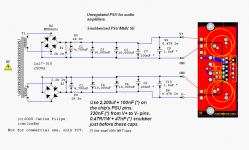
Two unregulated PSU schematics will do: one of the simple version (URS PSU), the other one of this SE version (URCRCCS PSU 😱 ).
Another schematic for the latest regulated (RS PSU).
😎
Contact me when you need.
PS: thanks for giving a help here, while I'm killing my brains with %$#&%$#%# SQL Server.
nina said:My tranf is center tab 25-0-25. Not sure if it's already mentioned whereelse here how to use center tab tranf with the LM338 regs?
No, you can't.
Is it better to put a warning on the schematic?

This question is answered thousands of times...
And btw, this thread is about the unregulated PSU.

If we spread off-topic questions through different threads, imagine the pain for those who wanna make a search.
Nuuk said:
That's right, you can't use a centre-tapped traffo. You may be able to convert it to separate windings if you feel confident that you can do it safely! It has been explained how to do this on this forum if you care to search.
Otherwise you are stuck with the higher voltage rails but why do you want lower voltage rails?
Nuuk,
Thanks for your advice. I am using the 35Vdc for LM3875 but the heat sink get slightly warm. So, just think it would be safer to use lower voltage (with minimum cost) to avoid the SPIKE protection activate. Just wonder if I should continue with the 35Vdc *i.e. not harmful) or buy new 18-0-18 trafo instead?
( My speaker is 88 dB and living room is only 4 x 5 metres ).
carlosfm said:
No, you can't.
Is it better to put a warning on the schematic?
This question is answered thousands of times...
And btw, this thread is about the unregulated PSU.
If we spread off-topic questions through different threads, imagine the pain for those who wanna make a search.
Carlos,
so, .... the 1,001st should be still okay 😀 heeheehee ( just kidding).
Thanks anyway ( I will give you an MCDBA ..... via the text )
😀 😀
Thanks for your advice. I am using the 35Vdc for LM3875 but the heat sink get slightly warm.
If you do mean 'slighty warm' then you have nothing to worry about. If it does get too hot, you will notice that it reduces the volume until the chip cools down. When that happens, you do need to get a larger heatsink. A well-impimented LM3875 won't need a very big heatsink!
Nuuk said:
If you do mean 'slighty warm' then you have nothing to worry about. If it does get too hot, you will notice that it reduces the volume until the chip cools down. When that happens, you do need to get a larger heatsink. A well-impimented LM3875 won't need a very big heatsink!
I see, Nuuk. Thanks.
BTW, I measures the Vdc at full load is +/- 38VDc on the Carlos snubberized PS MkII). Is that too close to the limit of LM3875 (+/- 42 V) ?
hello Nuuk thanks for your reply
i understand a lot better now about the voltage on the cap in regards to the psu dc output. since i only know the very basics of electrics. but this forum will help a lot more to understand it all
my speakers are Castle Howard s3 here`s the link
http://www.castle.uk.com/pages/classic_howard.htm
my current amp is a Cyrus 7 with a PSX-R witch is a about 70w RMS
so if i can make any GC sound as good Cyrus 7 with all the help on the forum . I`am listening to my GC now and getting better each day goes by plus it`s ony a few days old and fully burn in yet
I`ve looked at carlosfm design and thought this mite be better.
since the GC amp PCB has two grounds - & +
Plus the first time i put a transformer with only 3 wires for the out put on the rectifier pcb the transformer buzzzzzz very loud .
So i did open heart surgery on the transformer and separated the two output coils. And added a four wire so i go two output coils and all works wel without a very loud buzz from the tranformer.
I hope carlosfm don`t mind me changing his design a bit without his permission on this pic than i`ve added .
If you do carlosfm i will not do it again sorry
many thanks Scooby300
Attachments

BTW, I measures the Vdc at full load is +/- 38VDc on the Carlos snubberized PS MkII). Is that too close to the limit of LM3875 (+/- 42 V) ?
No, don't worry. We have high mains voltage here and my GC's have been running at +/-38 volts with no problems at all. 😉
In order to try and avoid confusion, and save Carlos some grief, I have added a snubberized page to the Gainclone pages on Decibel Dungeon.
Please note that DD is only updated on the Tiscali server now so please adjust your Bookmarks/Favorites. 😉
Please note that DD is only updated on the Tiscali server now so please adjust your Bookmarks/Favorites. 😉
scooby300 said:
I`ve looked at carlosfm design and thought this mite be better.
since the GC amp PCB has two grounds - & +
Plus the first time i put a transformer with only 3 wires for the out put on the rectifier pcb the transformer buzzzzzz very loud .
So i did open heart surgery on the transformer and separated the two output coils. And added a four wire so i go two output coils and all works wel without a very loud buzz from the tranformer.
I hope carlosfm don`t mind me changing his design a bit without his permission on this pic than i`ve added .
If you do carlosfm i will not do it again sorry
many thanks Scooby300
NEW!!!! pic becuse one of the rectifiers was the wrong way around plus i`ve only got one transformer with two outputs
Attachments
Where to get 0R47 resistors?
Hi Guys,
Does anyone have a good source of the 0R47 ohm 1W (or 2W) resistors that aren't inductive?
The only ones I can find in the electronic shops in Australia are the white coffin type ones (that start at a minimum of 5w anyway, which is too big).
I don't care what "brand" they are, I just want to find them.
I need 18 of them only.
Thanks.
Hi Mangrovejack,
You can find 2W 0R47 fusible resistors at WES components - they're in Sydney though! Or use 2x 1R 1W garden variety.
Just up the road at Bribie so know mangrove jack.
Greg
You can find 2W 0R47 fusible resistors at WES components - they're in Sydney though! Or use 2x 1R 1W garden variety.
Just up the road at Bribie so know mangrove jack.
Greg
Thanks for the reply Greg.
I was thinking of two resistors, but for my layout I want compactness and didn't want to add more components than I needed.
Yep mangrove jack are great fish. They put up a good fight.
I was thinking of two resistors, but for my layout I want compactness and didn't want to add more components than I needed.
Yep mangrove jack are great fish. They put up a good fight.
Just another question to ask. I know you guys are probably sick of hearing questions regarding "can I use this value instead?", but I'm going to ask one anyway 
Originally Carlos mentioned using 100uF + 100nF at the pins of the positve and negative inputs into the chip, but now with this latest revision, he mentions 2200uF + 100nF at the pins. Now that's a substantial difference. My question is, would 1000uF (Kind of a compromise I guess between the two values) be ok? I mean is it that critical (in terms of affecting the snubber also placed at the pins)?. I assume it would be ok, and since I haven't implemented my design yet, I just wanted to clarify.
The reason I wanted to use 1000uF is because I've got a whole lot of some nice Nichicons that I wish to use instead of having to go out and buy some new 2200uFs, which will also affect the design of my PCB's due to their increased size.
1000uF is going to be 'OK'. In fact Carlos suggests values from 1000 to 2200 for the regulated snubberized supply.
Try it and see and then if you feel like experimenting, go with the 2200uFs! 😉
Try it and see and then if you feel like experimenting, go with the 2200uFs! 😉
- Status
- Not open for further replies.
- Home
- Amplifiers
- Chip Amps
- The (high-cap.) unregulated PSU for chipamps