The voltage drop depends on the load and it's insignificant, in any case.
Most of the capacitance is after those resistors, and should cope with the amp's demands.
I have tested when listening loud, with heavy bass music, and the voltage drop of the whole PSU was between 0,5v to 1v (in extreme passages).
Quite normal, those resistors are not changing this.
Most of the capacitance is after those resistors, and should cope with the amp's demands.
I have tested when listening loud, with heavy bass music, and the voltage drop of the whole PSU was between 0,5v to 1v (in extreme passages).
Quite normal, those resistors are not changing this.
Carlos,
I was wondering if you have probed around the bridge with a scope and found any ringing from the diodes ? Have you tried a snubber between the trafo and bridge ? Simulation shows ringing around 250KHz; inductance of the trafo and switching of the MUR860s (this may not occur in reality as I admit that my trafo model may not be realistic). 100R/100n seems to do the trick at a snubber.
Regards,
Jon

Hi carlosfm,
I think you need to "date stamp" your circuits so we all know which is the latest. 😉 Might save a bit of the confusion for those not following closely.
Even better would be to have them available from a web site, if only there was a web site dedicated to building Gainclones you could use. 😕
I think you need to "date stamp" your circuits so we all know which is the latest. 😉 Might save a bit of the confusion for those not following closely.
Even better would be to have them available from a web site, if only there was a web site dedicated to building Gainclones you could use. 😕
Re: Update
hi carlosfm
i am new to this forum and just built my first GC from a LM3875 Amplifier Kit that i bought of the net it sounds ok. Will this psu design make sound any better than the one that came with the kit. And is the LM4780 Amplifier Kit any better than the LM3875 kit.
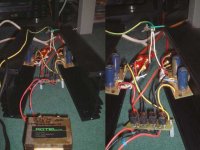
The transfromer is a old rotel one out of a dead amp. ac out is 27.4v @4 amps dc out is 35.9v @? amps it goes to high for my multimetre to read it . i`ve added a pic of my GC amp
it mite be bit a silly question but what are voltages are the caps on your design or does depend on the psu from the transformer voltage output

sorry it would not send pic so had to do again
many thanks scooby300
hi carlosfm
i am new to this forum and just built my first GC from a LM3875 Amplifier Kit that i bought of the net it sounds ok. Will this psu design make sound any better than the one that came with the kit. And is the LM4780 Amplifier Kit any better than the LM3875 kit.
The transfromer is a old rotel one out of a dead amp. ac out is 27.4v @4 amps dc out is 35.9v @? amps it goes to high for my multimetre to read it . i`ve added a pic of my GC amp
it mite be bit a silly question but what are voltages are the caps on your design or does depend on the psu from the transformer voltage output
sorry it would not send pic so had to do again
many thanks scooby300
Attachments
Lets do Hiend ! 😀
Carlos, a few questions:
1) The values of the snubbers, what relationship they have with
the values of the main PS caps ? Eg should i change them when
i have eg: 2200uF + 1R + 2200uF after the diodes ?
(The old 1R+100n and the new 0R47+1.5nF seems very different)
2) If the pins of the last 2200uF goes directly to the IC powerpins,
should i also use the another 2200uF+100n+(0R47+47nF) there ?
3) The 1R resistor between the big caps, what type is the best here ?
Can i use 5W wire-resistor, or its inductivity isnt a good practice here ?
Thanks !
In view of what Carlos said yesterday, and he dies have a job and a family (I don't), I'll try and answer a few questions.
Scooby300. The snubbered PSU should improve any chip ampBUT how much it does depends on the speakers that the amp is driving. People with 'easy to drive' speakers find less of an improement than those with 'harder to drive' types.
The rating of the capacitors depends on the rail voltages. If you have 37 volt rails, a cap going from one rail to the 0 volt rail should be rated for 37 volts and to be safe, you should multiply that by 1.25. That makes 46 so you would use caps rated for 50 volts.
Is the LM4700 better than the LM3875 kit. Other components being equal, there is little difference between the LM chips. Again, much depends on how much power that you need, and therefore once again, the speakers are a major factor in choice of chip. 😉
Cortez,
1) Carlos has been kind enough to share this design with us but understandably doesn't want to give away all his 'trade secrets'. So he will tell us what values of snubber he uses but not how to work them out.
2) The 2200uF caps go on the pins of the chip, ie they are the last caps.
3) I use 1 watt carbon film resistors on my snubbers (purchased from Farnell). If you want 2 watt rating, you could use two 1 watt types in parallel. 😉
Grege,
I agree it can get quite confusing if you are not following these threads from day to day. IF it is no extra work for Carlos, I would be happy to host these cicrcuits on Decibel Dungeon. In fact, I must write up the snubbered PSU there soon. 😉
I agree it can get quite confusing if you are not following these threads from day to day. IF it is no extra work for Carlos, I would be happy to host these cicrcuits on Decibel Dungeon. In fact, I must write up the snubbered PSU there soon. 😉
> understandably doesn't want to give away all his 'trade secrets'
Ok, i didnt know thats his job, i thought its just a hobby for him.
> The 2200uF caps go on the pins of the chip, ie they are the last caps.
I mean if my PS looks like this: trafo-diodes-2200uF-1R-2200uF,
and then the last 2200uF cap's pin would go to the IC's power pins,
then should i use one 2200uF more with one more snubber too ?
I mean if my PS looks like this: trafo-diodes-2200uF-1R-2200uF,
It doesn't really matter how many caps you have but the last ones must be right on the pins.
It is a hobby for Carlos but for reasons best left alone here, he doesn't want to put everything that he knows on forums. 😉
> It doesn't really matter how many caps you have but the
> last ones must be right on the pins.
I know, but when i put the my PS unit very close to the IC,
and the last elco caps legs can reach the IC's pins, there is
no need to another 2200uF +2nd snubber etc at the IC, isnt ?
> last ones must be right on the pins.
I know, but when i put the my PS unit very close to the IC,
and the last elco caps legs can reach the IC's pins, there is
no need to another 2200uF +2nd snubber etc at the IC, isnt ?
grege said:I think you need to "date stamp" your circuits so we all know which is the latest. 😉 Might save a bit of the confusion for those not following closely.
There's a version on each schematic.
I could include the date...
grege said:Even better would be to have them available from a web site, if only there was a web site dedicated to building Gainclones you could use. 😕
No time for that...
This thread is on a website.😀
I know, but when i put the my PS unit very close to the IC,
and the last elco caps legs can reach the IC's pins, there is
no need to another 2200uF +2nd snubber etc at the IC, isnt ?
Well, only you can decide if the last cap is 'on' the pins. If you think it is then no you don't need another cap/snubber. 😉
Re: Lets do Hiend ! 😀
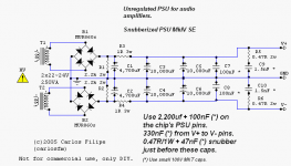
2,200uf before the series resistors is fine.
After, 4,700~10,000uf caps in parallel, for a total capacitance or around 20,000uf.
If you want a serious amp that drives most speakers AND sounds brilliant, this is the way.
Other combinations with caps and snubber values you can make, but I can't see the point in using low capacitance.
Yes, and this will make some that still prefer the low capacitance PSU to reconsider.
Those who are using a snubberized PSU, try these values.
The 1.5nf cap is not so critical, but a low value (lower than 10nf) is needed.
1.5nf sounds very very very very very good.
You guys like to gold-plate every pill...
Carbon is fine.
No wire-wound resistors for the snubber.
Cortez said:Carlos, a few questions:
1) The values of the snubbers, what relationship they have with
the values of the main PS caps ? Eg should i change them when
i have eg: 2200uF + 1R + 2200uF after the diodes ?
2,200uf before the series resistors is fine.
After, 4,700~10,000uf caps in parallel, for a total capacitance or around 20,000uf.
If you want a serious amp that drives most speakers AND sounds brilliant, this is the way.
Other combinations with caps and snubber values you can make, but I can't see the point in using low capacitance.
Cortez said:(The old 1R+100n and the new 0R47+1.5nF seems very different)
Yes, and this will make some that still prefer the low capacitance PSU to reconsider.
Those who are using a snubberized PSU, try these values.
The 1.5nf cap is not so critical, but a low value (lower than 10nf) is needed.
1.5nf sounds very very very very very good.
Cortez said:3) The 1R resistor between the big caps, what type is the best here ?
Can i use 5W wire-resistor, or its inductivity isnt a good practice here ?
You guys like to gold-plate every pill...
Carbon is fine.
No wire-wound resistors for the snubber.
Ok, i'am just confused cause the 2 snubbers values are different
(at the PS, and at the IC) so i dont know which snubber value
is ideal when i dont use the extra 2200uF + snubber on the IC.
In my design it would be only one elco-cap unit (2200uF + 1R + 2200uF)
and therefore just one snubber, cause the 2nd 2200uF will be already
connect directly to the IC's power pins. I hope its understandeable! 😀
Other: (HalfOff)
I found a topic about current source chipamps:
http://www.diyaudio.com/forums/showthread.php?s=&postid=649435
It should be here at chipamps, rahter then at the loudspeakers, shouldnt ?
May i open a new thread here at chipamps with this theme, or what ?
Cortez said:Ok, i'am just confused cause the 2 snubbers values are different
(at the PS, and at the IC) so i dont know which snubber value
is ideal when i dont use the extra 2200uF + snubber on the IC.
In my design it would be only one elco-cap unit (2200uF + 1R + 2200uF)
and therefore just one snubber, cause the 2nd 2200uF will be already
connect directly to the IC's power pins. I hope its understandeable! 😀
In that case, forget the 2,200uf cap recommended for the chip and it's snubber.
But I wouldn't use such a low capacitance for a CRC PSU.
carlosfm said:The voltage drop depends on the load and it's insignificant, in any case.
Most of the capacitance is after those resistors, and should cope with the amp's demands.
I have tested when listening loud, with heavy bass music, and the voltage drop of the whole PSU was between 0,5v to 1v (in extreme passages).
Quite normal, those resistors are not changing this.
Hi Carlos,
Refer to this PS version
I'd like to reduce the Vdc from 37Vdc to ~30V without changing my 25-0-25 transformer, can I use 5R (or 10R?) 5W (or 10W?)as the replacement of R3 and R4?
PS: I use one PS for both channels.
nina said:Hi Carlos,
Refer to this PS version
I'd like to reduce the Vdc from 37Vdc to ~30V without changing my 25-0-25 transformer, can I use 5R (or 10R?) 5W (or 10W?)as the replacement of R3 and R4?
PS: I use one PS for both channels.
Don't do that, it will not work the way you want because voltage drop will be higher when the amp demands more current.
The voltage you want to drop is too much.
You can regulate for ~28V with LM338 regs.
Or you can unwind some turns of wire from your trafo, or wind new wire in reverse direction, to lower the voltage.
This is the easy way.
- Status
- Not open for further replies.
- Home
- Amplifiers
- Chip Amps
- The (high-cap.) unregulated PSU for chipamps