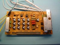
Here you see the Premotec in the SG1.
http://www.spiral-groove.com/Spiral_Groove/SG_1.1_files/_1030473_1.JPG
http://www.spiral-groove.com/Spiral_Groove/SG_1.1_files/_1030473_1.JPG
MiiB,
Without seeing your drawing of the air bearing it sounds like you are calculating using the entire surface area of the platter as the bearing surface. In Joachim's instance the bottom of the platter is not flat but machined for the bearing assembly and has a large recess cut into the surface.
If the rim is the seal, you can use the entire area for the calculation.
jn
Hi,
I've hardly seen a pancake motor (Scheibenläufer) used as drive. No cogging, low inertia and high torque from lowest speeds on, it seems like the ideal motor for a heavy belt driven platter to me.
jauu
Calvin
I've hardly seen a pancake motor (Scheibenläufer) used as drive. No cogging, low inertia and high torque from lowest speeds on, it seems like the ideal motor for a heavy belt driven platter to me.
jauu
Calvin
I've yet to find a better solution than a Premotec AC motor run directly via a large mains fed 110v transformer with the benefit of viscous drag in the main turntable bearing for some consistent load.
Beats a Hercules, beats a Lingo, beat all the Original Live DC rubbish, even beat my SME 10 and by the smallest of margins the German DIY AC 24v regenerator (the phase and voltage variable unit- it's very good)
Beats a Hercules, beats a Lingo, beat all the Original Live DC rubbish, even beat my SME 10 and by the smallest of margins the German DIY AC 24v regenerator (the phase and voltage variable unit- it's very good)
You mean whire the premotec for 220v and feed it with 110v ?
I got good results with that method in my rega and also with a micro seiki, but the rd80 seems to loose some "bite".
The noise from the motor with 110v is "invisible" and that enhances micro detail, but the lack of torque results in some bass bluring...
I got good results with that method in my rega and also with a micro seiki, but the rd80 seems to loose some "bite".
The noise from the motor with 110v is "invisible" and that enhances micro detail, but the lack of torque results in some bass bluring...
Hi sq225917 & RC
I am in need of a motor for TT project. but don't really do electrics, but handy with an iron, so could you do a step by step wiring guide to the Premotec plus where to get one, & approximate cost.
Jay
I am in need of a motor for TT project. but don't really do electrics, but handy with an iron, so could you do a step by step wiring guide to the Premotec plus where to get one, & approximate cost.
Jay
RC, I mean use a 120v Premotec and feed it 110v. I've done a lot of tweaking with the Premotec, measured speed stability using an RF demodulation of a 3150hz tone. There's some pics and measurements in there.
LP12 /Kuzma turntable PSU - a set on Flickr
If you want the least noise then yuo simply have to trim the phase for each motor, the nominal value is never that quiet. Also i find that equal voltage on both phase = less noise and if you load the motor, (with thick bearing oil in my case) the drag swamps the cogging and smooths out rotation further.
Jay, all you need you'll find in the link about, wiring diagram and annotated photo's.
Thanks for that link. This solution is really simple.
I had a meeting with Dominik today and gave him the brass platter.
He is working on a strong bearing that can carry this platter.
He showed me some Wolfram Carbite spheres.
The current idea for the mirror is sintered bronze in oil.
He also talked to Pabst if they have a fitting motor.
Anyway, we can always use the Premotec.
If you want the least noise then yuo simply have to trim the phase for each motor, the nominal value is never that quiet. Also i find that equal voltage on both phase = less noise and if you load the motor, (with thick bearing oil in my case) the drag swamps the cogging and smooths out rotation further.
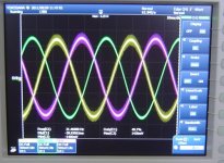
Second that. See attached the fully adjustable sine wave generator and scope shot of the output voltages (after adjustment) of my 30 year old EMT 928. Yes, its not their top model but it does an excellent job. And the adjustment is really important.
On a side note, for large (three-phase) motors in industrial installations, imbalances between the phases translate to torque ripple - guess why the utility companies have introduced regulations for minimizing the imbalance 😀
Attachments
Thanks for that link. This solution is really simple.
I had a meeting with Dominik today and gave him the brass platter.
He is working on a strong bearing that can carry this platter.
He showed me some Wolfram Carbite spheres.
The current idea for the mirror is sintered bronze in oil.
He also talked to Pabst if they have a fitting motor.
Anyway, we can always use the Premotec.
I love a good Pabst motor (always did, always will 🙂). And I do like a high torque motor. Will there be a electronic speed control, e.g. using a DC/AC converter, in that case the 2nd phase could also be electronically synthesized. Something like a Ardunio device could be used to control a quarts locked signal generator, devices like the OPA551 can be used to drive a transformer that outputs the motor power.
Easy.. to cheap out on the neutral conductor.🙂On a side note, for large (three-phase) motors in industrial installations, imbalances between the phases translate to torque ripple - guess why the utility companies have introduced regulations for minimizing the imbalance 😀
jn
I love a good Pabst motor (always did, always will 🙂). And I do like a high torque motor. Will there be a electronic speed control, e.g. using a DC/AC converter, in that case the 2nd phase could also be electronically synthesized. Something like a Ardunio device could be used to control a quarts locked signal generator, devices like the OPA551 can be used to drive a transformer that outputs the motor power.
Your love for Pabst motors is shared 🙂
Probably the best way to synthesise low distortion, controlled phase shift sine waves is with a dsp chip. It sounds complicated to build from scratch but there are some pretty cheap DSP oscillators on ebay and the Arduino needs to only control those. That is if this project settles on an ac motor.
Ohh. I have quite a few few PABST the 2 pole hysteresis motor, I don't think any motor better that that really exists. the "ausenlaufer"
Ohh. I have quite a few few PABST the 2 pole hysteresis motor, I don't think any motor better that that really exists. the "ausenlaufer"
So cool, yes I want an "ausenlaufer" yes yes ... 🙂
http://www.maschinenmarkt.vogel.de/...ebstechnik_steuerungstechnik/articles/185002/
Last edited:
- Status
- Not open for further replies.
- Home
- Source & Line
- Analogue Source
- The Good Turntable