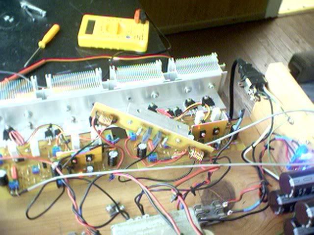
I took the time to build a variable power supply that goes from 5 to 30V. I always start a new design on 5 volts to see if there is a fault.
I did these things , but still #@%&ed UP!!😡
An externally hosted image should be here but it was not working when we last tested it.
BTW, thats a NJW0281..1/4" die. Still , I only blew 2, 1-0281
and 1- 0302. the other two survived and are now running in
the blown amp. I found out what I did (didn't) do which
is very important after frying ones first OP's. Duhhh, I didn't
screw down one of the 0281's, it thermally "ran away" and
POP.. out went the fuse.
In the end 2 amps are blasting away.(one channel w/only 2 OP's)
After surviving the whole album of "classical thunder".. WOW
(1812 overture clean)bye bye frugalamp 1, hello FA2.
The bass is incredible compared to the "blameless" with a
non-stressed smooth midrange and those same ear tingling highs
of FA1. A MUCH better sounding amp than the first one.
For some reason it runs much cooler than the original ,too,
even as both amps are biased the same (60ma/device).
Since I think I'll stick with this one, BOM, PCB,and detailed
layout is due to follow..

OS
Tough luck. In every battle there can be causalities though. I have a few fallen soldiers myself.
What are you doing the layout with? Eagle? I'm looking forward to seeing how you puzzle the puzzle 🙂
What are you doing the layout with? Eagle? I'm looking forward to seeing how you puzzle the puzzle 🙂
Actually doing it by hand with PSP7 and an assortment ofWhat are you doing the layout with? Eagle?
"TUBES" (donuts ,pads,etc) so I can do it MY way..
OS
An externally hosted image should be here but it was not working when we last tested it.
Here's the board..300 DPI ,4.5" X 6",active components keyed.
0 errors.. it's playing right now.
An externally hosted image should be here but it was not working when we last tested it.
Merry XMAS..
OS
Sounds Nice , no real flavor to it's sound (very little H2) great bass.
electrically it has >2MV (before trim ,after .2MV)offset, no turn
on/off thump , dead silent , and seems to stabilize well thermally.
Sounds like a bigger faster Symasym (I built that).I only have
been running it for a day now, but it seems to be very stable.
I have included extra pads on PCB for differential comp. and
VAS/OP comp (like symasysm) so any future anticipated
improvements can be realized.
OS

 ostripper
  that was hard on PSP
Sterling designs, guys, both the Frugal2 and the Abom!!
Hats off to you guys, outstanding work......
Hugh
Hats off to you guys, outstanding work......
Hugh
Thank you for inspiration, Hugh. I think I'll stick with this one
and just play with the comp. to get that "golden sound".
With the "real thing" in the living room now, I can do some
real world live assessments of this topology.Maybe I'll port it
out to a IRF (FET) OPS or CFP arrangement.
Electrically, it is the most accurate thing I've seen (sub 1mV
offset) NO noise ,turn on thump or anything but I always
want more (famous amp fetish). So any nested FB or
associated "tricks" would be welcome and tested "live".
OS
😉
Good looking board OS. I like the sideways mounted emitter resistors and I really like how the silkscreen has the component values. This saves so much time and more than one mistake during assembly. You have completed a winning design here.
Happy listening.
Happy listening.
lineup said:headphones method 😎
yes, i have used this.
once i did not use any output capacitor 😱
and so my great Sony Fontopia earphones was burnt and destroyed.
Regarding listening testing, using headphones at the amplifier output
resembles to a doctor listening to your heartbeat, in a stetoscope.
And this gives a better sound quality and judgement, than using speakers
which have a magnitude higher distortion.
Besides, when listening through loudspeakers, your room will be a part of the performance, too.
I never connect the output transistors at first switch on.
I just loop the VAs output back into the LTP and setup output offset. I then set the bias to minimum volts before connecting teh outptu stage.
By MJL - Good looking board OS. I like the sideways mounted emitter resistors and I really like how the silkscreen has the component values. This saves so much time and more than one mistake during assembly. You have completed a winning design here.
thank you. Mjl , if I post the one I want for myself(70's style) ,can you do "something" new year surprise.. 😀 (you know what I mean)
here it is..
An externally hosted image should be here but it was not working when we last tested it.
By nigel - I just loop the VAs output back into the LTP and setup output offset. I then set the bias to minimum volts before connecting teh outptu stage.
I do that too, but was a dummy and forgot to screw down a OP device😡 blew 2

Nice job ostripper... but I couldn't imagine the torture of doing a layout in a paint package ever again!
Here is my attempt after only an hour or two. I made a few tweaks as well - namely fuses on the PCB, and a resistor filtered rails for the small signal stages - nothing major!
I made my 70mm depth quota, but there is oodles of width... i will probably shove a protection circuit + relay on there too.
Do the ground a little bit differently (star from VAS and inputBy jaycee - Nice job ostripper... but I couldn't imagine the torture of doing a layout in a paint package ever again!
ground)and your good to go.
It only took about 2-3 hours total for me to make all 3
layouts on psp, about an hour a piece.
OS
Good to see that andy_c has explained how to simulate the loop, and open loop gain of the amp for the new guys here, should result in better designs. Keep in mind that the devices are much slower large signal and especially coming out of saturation.
Pete B.
Pete B.
By PB2 -Good to see that andy_c has explained how to simulate the loop
Yes, very helpful in design work, but it opens up even more
😕 questions.
I seem to have a very stable and loud amp with a great soundstage having only Cdom as compensation but that
is confusing as FA2's "little brother" (symasym), Ampslab's
BI 120/240 ,and most the other "blameless" type amps
in DIY land use other compensations often unknown to even
their creators.(I've asked)
This will not do, as I must know the "secret".
The first of the compensations is the NFB loop capacitor, I've
seen this one on the majority of class B amps, both DIY
and commercial.
An externally hosted image should be here but it was not working when we last tested it.
Notice how it shoves the UG point into the MHZ range and
changes the phase considerably. Andy C. noted that It
produced a "2 pole response" and I should dump it. BUT ,
why is it used so widely in designs??😕
It's effect is most pronounced...
An externally hosted image should be here but it was not working when we last tested it.
The second comp. is more complex, the RC in the differential.This
comp. (one DIY designer said he found it in a book and included
it in his design ???)But why?..
It's inclusion seems only to shave some gain off HF (5mhz+)
Some have commented that it changes H3,5,7 content but
this amp has almost none of that...
An externally hosted image should be here but it was not working when we last tested it.
The 3'rd comp. is explained in Self's book and is "down and dirty"
Gross shunt comp....
An externally hosted image should be here but it was not working when we last tested it.
Reduced OLG, unity gain point, loaded down VAS..
An externally hosted image should be here but it was not working when we last tested it.
This one I have actually implemented , and it reduces HF "brightness" , rounds off square waves , and produces more
H2. Why is it used on the "symasym" ...,to give it its sound ,or to
compensate for the shortcomings in the design ?? (both me and
MJL21193 had problems with symasym modelling)
Just for laughs I modelled all 3 mods simultaniously and
saw something totally different.
The comps seemed to cancel each other out increasing both
phase margin and UG while lowering the OLG..
An externally hosted image should be here but it was not working when we last tested it.
This mystery seems to cry out to be solved, some have solved
it but won't "give up the ghost" (Ampslab's M. chau explained
that he "doesn't have time to teach idiots how to design audio amplifers"..Quote)
OS
- Status
- Not open for further replies.
- Home
- Amplifiers
- Solid State
- The Frugalamp by OS