Clipping.
How to deal with this?
Some like to put in something to act when clipping occurs.
Even some soft clipping things.
Now, I deal not with clipping.
That is, I do not run amplifiers into clipping.
If you do, you have not enough power in your amplifier to handle your Speakers.
Time for an upgrade!!!!!!!!! 😀
What I can think of, is to use some sort of warning.
Clipping indicator, in form of a LED
This LED will turn on at for example -3dB before clip.
This is something I have seen in several power amplifiers.
MJL21193 said:I improved the clipping greatly by dropping the current through the VAS from ~10mA to ~2mA. It still sticks but it's much cleaner now.
A method for improving clipping behavior
Attachments
Redid FA2  at your exact conditions (+-30) and guess what.....
On the first sim I also had ringing on SW (heavy)
I now know why as well. LTP is saturated at this voltage level (30V),
if you drop the 33k's to 22k (like symasym) ,amp again models
absolutely perfectly again (also dropping VAS to 5.5mA (VAS Re 82R). Vbe at this voltage also goes WAY underbias..
The fact that it even worked at +- 30v surprises me as Sim
nearly crashed first run.
Run it +- 50 to +- 75 V and then show us again. Awesome that you built it before me (as predicted), but don't give it a bad name by running it so out of spec.
An interesting note.. when I shut FA1 off with music playing
I hear it's last gasp (static sound) at around 30V before the amp fully shuts down (not the point in time I would prefer to
do my benchmarks).
OS
at your exact conditions (+-30) and guess what.....An externally hosted image should be here but it was not working when we last tested it.
On the first sim I also had ringing on SW (heavy)
I now know why as well. LTP is saturated at this voltage level (30V),
if you drop the 33k's to 22k (like symasym) ,amp again models
absolutely perfectly again (also dropping VAS to 5.5mA (VAS Re 82R). Vbe at this voltage also goes WAY underbias..
The fact that it even worked at +- 30v surprises me as Sim
nearly crashed first run.
Run it +- 50 to +- 75 V and then show us again. Awesome that you built it before me (as predicted), but don't give it a bad name by running it so out of spec.
An interesting note.. when I shut FA1 off with music playing
I hear it's last gasp (static sound) at around 30V before the amp fully shuts down (not the point in time I would prefer to
do my benchmarks).
OS
ostripper said:
Run it +- 50 to +- 75 V and then show us again. Awesome that you built it before me (as predicted), but don't give it a bad name by running it so out of spec.
Be cool OS,
The feedback and input resistors in mine are not 33k. I raised the input sensitivity so these are 27k. It should be running just fine at 30V.
I'm going to try roenders suggestion to see if that make an improvement but in the meantime you should look at lowering the current through your VAS. It doesn't need to be operating at that high current - look at the RMI, look at the symasym.
WOW , I even scaled it down to +- 20v (perfect SW and sine 20k)
😎 with the gain wrong (33k)and the wrong voltage (30V)
this mod allowed the FA2
to negotiate the sim without crashing (a "governer" on the gain)
a worthy addition (2 1n4148's???)
OS
by roender - A method for improving clipping behavior
😎 with the gain wrong (33k)and the wrong voltage (30V)
this mod allowed the FA2
to negotiate the sim without crashing (a "governer" on the gain)
a worthy addition (2 1n4148's???)
OS
By MJL - It doesn't need to be operating at that high current - look at the RMI, look at the symasym
Full agreement at 5.5 MA(82 Re) VAS seems to stay linear over a much wider range of rail voltages (even with too much gain)
2sa1381's are smaller, faster devices(100mA), dont need as much
current as MJE350's (500mA)
27k seems to be just the "breaking point" on the sim whereBy MJL - 27k
things start to go right again(22k gets it back all the way)....(At 30V) widlar buffer also "likes" 2.2k (more linear VAS)
Don't worry, I'm cool,.. as I'll be able to "fire it up" with all the bugs already worked out...🙂
OS
ostripper said:
a worthy addition (2 1n4148's???)
OS
I tried it - A marginal improvement, but the real progress came from lowering the current through the VAS.
I crossed my fingers and connected to the big +/-72VDC supply. 😱
No smoke, no problems. Overshoot is still evident on the squarewave and it still sticks in clipping, more on the bottom than on the top but this is something that is hard to avoid I think.
Looks good OS. 🙂
Overshoot is still evident on the squarewave and it still sticks in clipping
I also saw this at Cdom 33/47p, I use 68p so maybe it will be better. in D.self's book even his best amps had a little overshoot before addition of RCL (zoble/inductor).
Glad it worked at 70V no

I will have to work on sticking..
ostripper said:
I will have to work on sticking..
I wouldn't worry about it too much. If the bad stuff can be avoided (signs of oscillation on the bottom wave during clipping as shown above). I have the VAS running at ~2.5mA per "leg" and there was no problem to drive my 8 ohm dummy load to clipping with the 72V rails (~45Vrms output - 253 watts into load)
I added clamps to the Patchwork to tame this and they work well but I think a better way is to avoid clipping all together by using a power supply that gives some headroom. Limit the output by raising the input sensitivity.
BTW, the DC offset is ~4mV on mine. Safe to ditch that pot if you want (I didn't include it).
I wouldn't worry about it too much. If the bad stuff can be avoided
No worries here.. I "thunk" it through, how ther could be overshoot on my "baby".... and here is a possible answer.
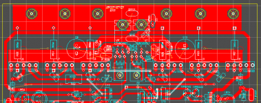
1. On your board (not to be critical), that big fat output "plane"
could be an is issue . I absolutely know this because I work
on the best anology to this... the switch mode power supplies
in my car amps,flat screen monitors, etc. I have noticed
by observing these waveforms (usually 10-15K square waves)
that the foil layout and component placement have a
definite effect on the waveshape in these power supplies.
With some of the better ones , I have even seen them induce
extra stray capacitances with the intent to keep harmonics down..
(RF design tricks).
2.This amp in simulation does good down to 39p before any overshoot is visable, but that is just a simulation.that is why I
chose 68p ,just for safety's sake.
3.When I did get the original "symasym" working, the "gross compensation" (68k/330p at VAS) is what kept the lid on overshoot
(even rounding the corners at 10-20K /while degrading slew)
maybe this is the reason for the smooth sound the design
seem to have.
4. Even with your "monster" OP plane ,a good zoble will
nullify it for the most part. I played with the widlar buffer
and at (5.5mA) 2.2k made the tiny clip in the sym
balanced (still this is just a sim) What I mainly noticed is
that with any given voltage careful adjustment of the
main Re (VAS 68R-82R) and the LTP Re's (47/68/100)
made things right again..(linear VAS/no overshoot)
All in all, we(I mean you) move much faster than some in
DIYland "power amp under development" went through a
dozen revisions before it was built.
Thank you for giving me a "first peek" at what I have to expect.
🙂 OS
I found out more.. Just simulations ,but they show certain errata.
maybe I'm crazy, but that spike at the end could be just the result of the 5 pf cap at the LTP , but it was nowhere as pronounced as it is now. Also,the initial OLG of this amp was
off the charts (the zetex's are single junction darlington's
says they are in datasheet, with hfe of 500 Minimum) So
I degen'ed the LTP some more to get the <60db gain as before
so Icould play with compensation. the zetex's are much higher in
gain but at the price of much higher Cob (6p).. thats
higher than the 1381's (2.3p)..
In conclusion, I fiddled with the zetex's and am glad I have my
6 cent 1845's they seem to be better for this application.
I did find away to tame your 696b's , degen the LPT Re's to 150/220 .And for a much better "rounded squarewave' add the
RC comp like the symasym...(100k/100p R/C)
PS ...Also you might want to get rid of that 5p cap at NFB...
OS
An externally hosted image should be here but it was not working when we last tested it.
maybe I'm crazy, but that spike at the end could be just the result of the 5 pf cap at the LTP , but it was nowhere as pronounced as it is now. Also,the initial OLG of this amp was
off the charts (the zetex's are single junction darlington's
says they are in datasheet, with hfe of 500 Minimum) So
I degen'ed the LTP some more to get the <60db gain as before
so Icould play with compensation. the zetex's are much higher in
gain but at the price of much higher Cob (6p).. thats
higher than the 1381's (2.3p)..
In conclusion, I fiddled with the zetex's and am glad I have my
6 cent 1845's they seem to be better for this application.
I did find away to tame your 696b's , degen the LPT Re's to 150/220 .And for a much better "rounded squarewave' add the
RC comp like the symasym...(100k/100p R/C)
An externally hosted image should be here but it was not working when we last tested it.
An externally hosted image should be here but it was not working when we last tested it.
PS ...Also you might want to get rid of that 5p cap at NFB...
OS
ostripper said:
No worries here.. I "thunk" it through, how ther could be overshoot on my "baby".... and here is a possible answer.
1. On your board (not to be critical), that big fat output "plane"
could be an is issue .
Ok. You need to back up a bit here and realize that not all will be revealed in simulation. It's not until you build the actual amp and look at it's output that you'll know for sure how it is performing. To expect a new design to run exactly as simulated is a bit out there.
Also, mine is running with 47pF Miller caps. Overshoot is common in under compensated amps. It would probably disappear if I were to use 68pF or 100pF. Not much would be lost as this amp is very fast anyway.
BTW, overshoot shows in my sim with 47pF Cdom.
Finally, my monster trace. Multisim has "trace width analysis" and it determines how wide a trace should be to carry the current it will see. Given that there are big holes through it for mounting screws, it isn't bigger than it needs to be. Besides, I built the Abomination with an even bigger output trace and it shows zero overshoot.
Attachments
ostripper said:
I did find away to tame your 696b's , degen the LPT Re's to 150/220 .And for a much better "rounded squarewave' add the
RC comp like the symasym...(100k/100p R/C)
PS ...Also you might want to get rid of that 5p cap at NFB...
OS
Degeneration for the LTP is 100R (I recognized the high gain of the ZTX) and I didn't have the 5pF in (problems with this before and I avoid it if I can).
I will increase the emitter R's to 220 and see how it looks.
Ok. You need to back up a bit here and realize that not all will be revealed in simulation
I'm not cracking on your board layout as it is beautiful (and the first), but only exploring various factors which could lead to a
better design (I have 18 blank FR4's left).
I don't back up, I will beat something till it works right...
I fully realize sims are only "approximators" and the "real thing'
always rears a few "ugly bugs".
Clipping and other simulations seem ill represented
(at least on LT).
I'm not sim happy, but it's crazy how I saw that Krappy 20khz
sine in my lowvolt sim this morning just as i saw it on your
CRO...
Those zetex's don't seem to be the "cheese".. how could I pay
1.56 for a part that does not seem as ideally suited for
a differential as a 6 cent 1.5pf ksa1845 ??
Did you build them with the zetex's???I built the Abomination with an even bigger output trace and it shows zero overshoot.
OS
I will "steal" it tonight.😎Multisim has "trace width analysis"
Got it....in 2 hours
Is yours ver. 9.xxx??
ostripper said:
Those zetex's don't seem to be the "cheese".. how could I pay
1.56 for a part that does not seem as ideally suited for
a differential as a 6 cent 1.5pf ksa1845 ??
Did you build them with the zetex's???
OS
High gain for the differential pair is desirable OS. Remember, gain is disposable - it's easy to throw some away that you already have. 🙂
The 696b's are beautiful, but your amp will run on lesser specimens. I wanted to have a good healthy high voltage capacity, so I used them. They are pricey but they were as close to identical for gain as my DMM will resolve. They also have higher dissipation (not needed really) and are flat on both sides for effective thermal coupling. I wouldn't use anything else for a simple LTP like this one.
The abomination was built with the cascoded BC550's which would have an hFe around 500 for the current through them. Degeneration was 100R.
Anyway, good news. The increase to 220R for the emitter resistors has killed the overshoot.

The new and improved 20k squarewave. There is a little squiggle on the flat part that's hard to see in the pic, but I think this can be cured with the higher Cdom (or not, it doesn't look like a big deal).
So, I guess it wasn't my "monster" trace after all...🙂
MUCH better , as predicted... as far as the zetex's ,Im sure they will be alright...as I only noted their effects on OLG,unity gain ,etc.
My "slower" 1845's might not need these changes.. I can
only wait till wed./thurs. to find out..
the VAS 1381/3503's have all the gain in this amp so
we throw almost all of it away with those 696b's
I read their app notes and it seem they are widely used
for HF switches , portable devices (switching oscillator in
a police tazor unit!!!😀 ) relay driver (high Ic),etc.
I am impressed that you got 4mA offset first bang..(they better be
matched for that price).
I am aready working on a new creation , the protection circuit..
Creating any offset over +-1v on either voltage source (DC prot.)
,chopping R1/2 (simulating Op device failure),or dropping R5
below 1R (short /5A) triggers U2's output high in 1uS (fast).
R4 adjusts sensitivity to trigger for different amps..
Next will be the logic gates and relay output section (which also
incorporates the soft start).
OS
My "slower" 1845's might not need these changes.. I can
only wait till wed./thurs. to find out..
yes, butRemember, gain is disposable
the VAS 1381/3503's have all the gain in this amp so
we throw almost all of it away with those 696b's
I read their app notes and it seem they are widely used
for HF switches , portable devices (switching oscillator in
a police tazor unit!!!😀 ) relay driver (high Ic),etc.
I am impressed that you got 4mA offset first bang..(they better be
matched for that price).
I am aready working on a new creation , the protection circuit..
An externally hosted image should be here but it was not working when we last tested it.
Creating any offset over +-1v on either voltage source (DC prot.)
,chopping R1/2 (simulating Op device failure),or dropping R5
below 1R (short /5A) triggers U2's output high in 1uS (fast).
R4 adjusts sensitivity to trigger for different amps..
Next will be the logic gates and relay output section (which also
incorporates the soft start).
OS
ostripper said:
I am impressed that you got 4mA offset first bang..(they better be
matched for that price).
It's due to my beautiful layout 😉
I never have offset above 15 to 20mV. If I did, I'd feel like a failure. It's the second thing I check after I fire up - first is idle current.
The 696b's are not matched, but just seem to be well manufactured. The spice models are known to be more accurate also. I don't know how noisy they are (probably negligible) and I have only used them on my big sub amp (which is also bootstrapped and has no turn on thump - thank the Gods ).
There aren't many options at this voltage.
Os you got a good point about the zetex parts, I think using them is counter productive. One has to keep in mind that the 696s gain is measured at 100ma and ltps are usually below 10ma. The japanese tranny will in all probability have higher gain than the zetex at the currents that is of interest here, plus offcourse youll have the benefit of a very low noise and low cob part. My stock of 992 1845 present gain of over 600 as it is but they are original NEC parts, one of my favourite low signal trannies. The japanese trannies arent any good for higher than 8ma use though. I dont know about the fairchild copies. Its also counterproductive to degenerate a the ltp further to accomodate the zetex parts as youll be raising noise too. I think youll find if you experiment with spice that a lower cob part will improve the overshoot, run some sims and change the cob value in a model to a lower value and compare. Very low cob values are highly desireable in current sources and mirrors too. The zetex parts are definetly not darlingtons, they would have to present gain figures far above 1000 if it were the case, just western misinformation attempt to be able to compete with japanese excellence in semiconductor manufacturing.
homemodder said:just western misinformation attempt to be able to compete with japanese excellence in semiconductor manufacturing.
Gee, not hard to figure out what you like, is it? 🙂
I doubt my DMM measures gain at 100mA 😉
I just measured a 2sC1845 (original NEC) and I have a reading of 427. The ZTX696B reads as 610.
Do you know of a suitable high voltage (140V+) replacement? I prefer to cascode so that I can use lower noise, lower voltage devices.
- Status
- Not open for further replies.
- Home
- Amplifiers
- Solid State
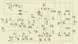
- The Frugalamp by OS