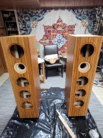
I used three (3) 1" countertops for the enclosure sides and back. Two were pre-finished from Lowes, about $240 each, the other was a unfinished worktop I bought on Amazon for $100, apparently the last one since the company stopped selling them. So fortunately did not to pay extra for shipping. The front baffles are 3/4" bamboo plywood boards, two (2) 12" x 48", about $50 each, and which are a shippable size via UPS ($40). There are a few sellers who offer them. The rest of the construction was Baltic birch plywood I picked up locally (Woodcraft). therefore I would say the material cost of the enclosures is about $800 for the pair. This is a premium build, obviously, using MDF would be substantially cheaper, even BB ply would be cheaper, but 1" BB ply is a bit more difficult to get (in retrospect, not as difficult as bamboo ply). I do like how bamboo plywood works compared with BB ply, with the right tools and sharp blades and bits.
David
David

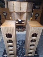
Cabinets are completed and now proceeding on finishing them. I consulted with a friend who is a professional finisher (mainly boats and yachts), who has extensive experience with various finishes, and he advised me on the prep sanding, various finish options, and technique as applicable to the selected finish. I wanted to avoid polyurethane, and settled on an polymerized tung oil/resin finish that uses a citrus oil solvent (low VOC) used on boat interior cabinetry. It builds up in several coats (wipe on/wipe off), dries fairly quickly, and does not require much of any sanding between coats (just wet sand with 600 grit before the final coats). For a sheen, apply carnauba wax overtop. He advised to use poly on the bottom of the cabinets first, so the speakers can be finished standing upright. Anyway attached is a picture of the speakers with the first coat of poly on the bottoms. IN a few days (hopefully) they will be complete and then off to assembly.
BTW, the speakers in the background are Basszillas (Platinum Edition), designed by Dick Olsher, that I built 15 years ago and now reside in the basement.
David
BTW, the speakers in the background are Basszillas (Platinum Edition), designed by Dick Olsher, that I built 15 years ago and now reside in the basement.
David
Attachments
David,
Good to see your rapid progress on the project.
I notice that you have some holes on the bottom of one the cabinets - these are for the base/stand?
Where are you planning to place the crossover? Given that your speaker bases have quite a bit of metal in the them, perhaps placing them away from the bottom will be something to consider.
Zman,
The holes are for mounting the outrigger feet. Not worried about the metal, it is aluminum, non-magnetic stainless steel, and brass, so unlikely to have any influence on the crossover network. I am mounting the crossover for the two lower drivers at the bottom, and the crossover for the tweeter (and inductor for the mid-bass drivers) on a board just above the terminals on the back panel.
David
David,
Some food for thought:
http://www.troelsgravesen.dk/coils.htm
https://www.diyaudio.com/community/threads/inductors-placement.280474/#post-4469922
Some food for thought:
http://www.troelsgravesen.dk/coils.htm
https://www.diyaudio.com/community/threads/inductors-placement.280474/#post-4469922
Zman,
The aluminum outrigger bars are 2 inches from the coils. The coils are mounted on a 1/2" plywood board, which is on a 1/2" standoffs from the bottom of the cabinet, and the cabinet thickness of 1". Based on the pictures, Joe sits his Elsinores directly on a substantial aluminum plate, and I believe his crossovers are mounted to the bottom of the cabinet, and the inductors actually could be closer that 2" to the plate.
I am only using one iron core(laminated) inductor in the network (L4), which is oriented horizontally, the rest are air cores, the big 3 mH is horizontally mounted. I pretty sure I am OK.
My crossovers are removable for upgrade later (including adding an external crossover).
David
Zman,
BTW, I forgot to thank you for the links you sent on the influence of aluminum in proximity of inductors. I was not aware of that. I always assumed ferro-magnetic material was the only thing to really be concerned about. I admit I was in defensive mode on my last postings since the crossovers are already built, the mounting standoffs already installed (glued on the cabinet) and pre-drilled for the crossover boards. So inconvenient to change anything right now unless it was a major fault.
As it the test results seem to indicate, a 25mm spacing between a vertically oriented cored inductor and an aluminum plate results a 2% reduction in the inductance value, which is probably within the tolerance of an off-the-shelf inductor, and certainly inexpensive LCR meters that a hobbyist would have checking. It would be interesting to see how much the value would change with a substantial field (high current thru the coil).
David
This is a really good driver. I use it in my 2.5 way tower. And I have been super impressed with both the tightness of the low end, and the ability to run with a First Order crossover (inductor only) up pretty high. And it is very flat with no noticable harshness from cone breakup up high. (Much better than my SB-17CRC in a two way bookshelf, which had really nasty cone breakup at 5k hz that I had to attenuate.)have another thought, the ULD is so expensive and there is one of the Satori drivers that would work well, the MW16P-8.
The Satori is good infact that I have decided to run with an external crossover so I can play with many different options/configs in the crossover, playing with different setups (all First Order, vs the lower midbass just used for baffle step, etc).
I think you would really be impressed with it in your Elsinores. And I like that it has a Neo magnet and very open back. (So beautiful, too bad it is obscured in a box).
I have considered cutting 2 more driver holes in my cabinets and going full Elsinore with my build, but I would need to order 4 more MW-16Ps...
Zman,
BTW, I forgot to thank you for the links you sent on the influence of aluminum in proximity of inductors. I was not aware of that. I always assumed ferro-magnetic material was the only thing to really be concerned about. I admit I was in defensive mode on my last postings since the crossovers are already built, the mounting standoffs already installed (glued on the cabinet) and pre-drilled for the crossover boards. So inconvenient to change anything right now unless it was a major fault.
As it the test results seem to indicate, a 25mm spacing between a vertically oriented cored inductor and an aluminum plate results a 2% reduction in the inductance value, which is probably within the tolerance of an off-the-shelf inductor, and certainly inexpensive LCR meters that a hobbyist would have checking. It would be interesting to see how much the value would change with a substantial field (high current thru the coil).
David
David,
Same here - I was not aware that aluminum could influence inductors; a few years back I was thinking about an aluminum baseplate for one of my speaker builds when I came across the Troels article. 🙂
Neither is copper magnetic, but if a current can be induced to flow in the aluminium plate, a resistive loss can be attributed to it.As it the test results seem to indicate, a 25mm spacing between a vertically oriented cored inductor and an aluminum plate results a 2% reduction in the inductance value, which is probably within the tolerance of an off-the-shelf inductor, and certainly inexpensive LCR meters that a hobbyist would have checking. It would be interesting to see how much the value would change with a substantial field (high current thru the coil).
The amount available to the plate is going to remain relative to the signal level, the most significant potential change being whether the inductor core material saturates and varies the amount of flux emanating beyond it. Of course, by then that will be the more significant concern.
I and some colleagues at work herenin sydney are thinking about building these as a project together, but were thinking about how one might make matching atmos height speakers, which need to be smaller even than the hamlet due to weight and height requirements.
Would an updated JR mini design which uses the newer SB acoustics or puri-fi drivers and The waveguide, or a version of the hamlet that uses a 5 inch driver be something that would be interesting to anyone. I would be willing to build enclosures, and supply drivers if Joe would be interested in helping with a crossover design.
Would an updated JR mini design which uses the newer SB acoustics or puri-fi drivers and The waveguide, or a version of the hamlet that uses a 5 inch driver be something that would be interesting to anyone. I would be willing to build enclosures, and supply drivers if Joe would be interested in helping with a crossover design.
Joe,
I have a question on port length for the ULD. I am using what is available here in the US as a 3" ABS slip-on coupling, which is 3.5" ID (89mm). I followed the construction guide that shows a 100mm long port. The port as installed is 3.875" long (98mm). However, I belatedly noticed that the ULD crossover diagram says a 75mm long port for the ULD. What is the consequence of mistuning with a longer port? Is this something I can adjust with damping? Or should I just cut it down to the proper size.
Thanks.
David
Ok, I ran some numbers using an online port calculator on the difference in tuning between a 100mm port (MFC) and 75mm port (ULD) lengths. Assuming as Joe suggests that the effective box volume (as stuffed) is around 100 liters (actual volume around 75 liters), I can see that for the MFC port, the tuning is around 33.5 Hz (I believe Joe mentions a 33 Hz tuning), and for the ULD, it would appear to be around a 36.5 Hz. Is that correct? I also see that Joe originally was starting with a longer port for the ULD build (130mm), but finally settled on a 75mm long port, and is even suggesting some intrepid volunteers to experiment with smaller ports from 50 to 70 mm in length (increasing the frequency further).
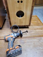
Anyway, circling back to my question above, how critical will this mistuning be on LF rolloff and perceived bass response (in combination with room gain)? Will this be a minor effect, or is it critical enough for me to change the port length now before completing my build. Fortunately, I have found a power drill driven internal PVC pipe cutter tool where I can set the blade to a 3 inch depth using the supplied depth guide and therefore should be able to cleanly trim the port to the recommended length from outside the enclosure.
David
Zman,
Yes. Since I thought it would be a 100mm (4") long port, the 3" (3.5" ID) ABS slip-on couplings are 3.125" long. So I routed out a 1/4" wide rebate around the 3-1/2" hole inside the back panel and epoxied it in place. So not able to remove it. Bad me. I should be getting the pipe cutter saw tomorrow and try it on a scrap piece of PVC tubing before I tackle the port. I first want to hear back from Joe before attempting surgery. I am so close to being done...I just put on the last coat of finish this evening, prewired all the crossovers in prep for driver installation, and tomorrow will cut all the Dacron batting.
David
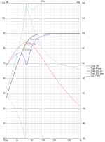
Sorry for this being a monologue, but I just installed VituixCAD to model the ULD LF response to better understand the influence of different port lengths on the response curve. Since the software has the Purifi PTT6.5W08-NFA-01 driver data, I used 4 in a series/parallel configuration into a 75 liter enclosure. I picked an enclosure damping Qa=10 (between a lined sides, Qa=20 to heavy fill, Qa=5). I also am using a minimal leak Ql = 15, though with as well built of a cabinet, I could get by with a Ql=30). So with a port diameter of 8.9cm, two flush ends (one flanged), and just varying the port length I get the following:
10cm port length, Fb = 36.8 Hz :

7.5cm port length (Fb = 39.9 Hz):

So it is subtle, but with the 10cm port, the f3 is higher at 50.4 Hz, but f6 and f10 are lower indicating a little better extension, and output a 20Hz is 2 dB higher (71dB). With the 7.5 cm port, the f3 is lower at 41.8 Hz, but there is a steeper rolloff with a slightly higher f6 and f10 frequencies. The response is about 1dB higher at 50 Hz (a little flatter in the passband)
It is really close, and I imagine the any preference between the two could be room and system dependent. I should go back and model the MFC version to see how it compares. But not sure I want to change anything at this point and give it a listen with the 10cm long port before the irreversible shortening.
Any observations? Which alignment, in your experience or interpretation would seem better from a transient response perspective. My guess is the longer port may be slightly better, but I may be wrong.
10cm port length, Fb = 36.8 Hz :
7.5cm port length (Fb = 39.9 Hz):
So it is subtle, but with the 10cm port, the f3 is higher at 50.4 Hz, but f6 and f10 are lower indicating a little better extension, and output a 20Hz is 2 dB higher (71dB). With the 7.5 cm port, the f3 is lower at 41.8 Hz, but there is a steeper rolloff with a slightly higher f6 and f10 frequencies. The response is about 1dB higher at 50 Hz (a little flatter in the passband)
It is really close, and I imagine the any preference between the two could be room and system dependent. I should go back and model the MFC version to see how it compares. But not sure I want to change anything at this point and give it a listen with the 10cm long port before the irreversible shortening.
Any observations? Which alignment, in your experience or interpretation would seem better from a transient response perspective. My guess is the longer port may be slightly better, but I may be wrong.
Okay, I looked at the MFC alignment with the 100mm long port with the same box parameters as above and it is interesting. f3 is 44.9Hz, f6 is 36.2Hz, f10 is 30Hz. The alignment does not dip below 200Hz a couple dB like with the Purifi drivers, and I think the 75mm port in the latter case minimizes the dip. So I now leaning shorten to port, the resultant alignment is closer to the MFC version.
David

David
Attachments
- Home
- Loudspeakers
- Multi-Way
- The "Elsinore Project" Thread