Maybe the polarity of the tweeter is reversed both at the speaker and in the crossover?
For the test, he can replace one of the points and perform the measurements again.
For the test, he can replace one of the points and perform the measurements again.
I have always had a hard time simplifying electric networks, just visually can't wrap my head around it. The only difference I can tell is where the L2 comes into play, but electrically I think it is the same. basically in my mind all the caps are wired after the l2 is wired. there are two solder points at the IN.I would check the connections again.View attachment 1148811
MTG90 assembled per the main EL-6 (MFC) crossover network (not the one you linked) and looking through it, it looked exact.
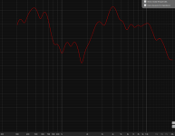
swapping tweeter poles does reduce performance more i think. green is as wired, red is after the swap. No clue. these are just 1 run each.
Attachments
Last edited:
I think I can close this out as room issues, honestly. If someone see's otherwise let me know. Taking near field measurements greatly improves the response, which makes sense. And testing each speaker with the mic "inside" the woofer, like past the surround, shows the crossover is working as intended.
After speaking with my friend (who I design speakers with) he mimicked my idea about it being a crazy room issue, based on how height dependent it is but then asked what the size of the tweeter was. Being a large dome, it suffers from off axis issues, which the wave guide should help, however:
I have put some cardboard under the box to angle the speakers up. What we are seeing below is most likely bass reinforcement due to being in a small room, combined with a lot of thicker foam which is naturally better at higher frequencies. The bass traps have reduced some nodes specifically at 68 and 95 as can be seen by the waterfall below. Sub 100ms decay time which is also pretty consistent. Raising the box also got rid of any sporadic mid range and high frequency issues so I think it is safe to say this was the issue. Sorry to drag everyone a long for this, but my intial hypothesis was room issues!
Not sure if I know what that is, but after searching, I think you want one of these?How does a gated measurement look?
https://www.minidsp.com/application...s/loudspeaker-measurements#gated-measurements
Look at this link. 🙂
Look at this link. 🙂

Oh I got close to doing that - that's the page I used but missed the point of it.
Ok here is response no smoothing without gate. Measurement taken 1m from tweeter height.

The issue I have is how messy it is, but the calcutlator shows 3.3ms for the first reflection.

Applying filter...

New graph

Not sure what this shows me, stil a reduction in energy, but much less.
Ok here is response no smoothing without gate. Measurement taken 1m from tweeter height.
The issue I have is how messy it is, but the calcutlator shows 3.3ms for the first reflection.
Applying filter...
New graph
Not sure what this shows me, stil a reduction in energy, but much less.
In REW you need to change the right window time so that it ends before the first reflection seen on the impulse response. This will gate out the reflections in the measurement and clean it up before the gate affects frequency resolution from approximately 1K down. 3.3ms is a short gate.
Doing in-room frequency response measurements is very tricky indeed.
Below is the "ULD" version and in my room. Both speakers are approximately 15 degrees off axis at the listening position which is where the Earthworks M30 omni mic was put. Non-coincident pink noise was used and energy with 1/6th of an Octave is then portrayed as vertical bars. Six bars equals one Octave.
For anybody walking through the door, give me a little bit of advance notice, I can demonstrate the following response and they can watch me do this measurement:

The above is at the listening position.
Now this is with twin SVS SB3000 subs (sealed box) and their affect is below 30Hz above which is is rolled off at a massive 24db/Octave. The peaks around 45 Hertz and trough around 85 Hertz and peak around 130Hz. these are room related and unaffected by the the two subs. This was carefully done and I have the equipment to set it up this carefully.

Below you can see the results with subs in and not.

These are 1/6th Octave RTA measurements. This is a matter of having the equipment to be able to do this.
Even though you may not able to do such a measurement, you can be pretty confident that if you have followed all the instructions, then the above should assure you of the result you have. Of course, if the room was taken away, then the response, particularly from 200 Hertz and up, would be even more flat.
I am just trying to be assuring.
Below is the "ULD" version and in my room. Both speakers are approximately 15 degrees off axis at the listening position which is where the Earthworks M30 omni mic was put. Non-coincident pink noise was used and energy with 1/6th of an Octave is then portrayed as vertical bars. Six bars equals one Octave.
For anybody walking through the door, give me a little bit of advance notice, I can demonstrate the following response and they can watch me do this measurement:
The above is at the listening position.
Now this is with twin SVS SB3000 subs (sealed box) and their affect is below 30Hz above which is is rolled off at a massive 24db/Octave. The peaks around 45 Hertz and trough around 85 Hertz and peak around 130Hz. these are room related and unaffected by the the two subs. This was carefully done and I have the equipment to set it up this carefully.
Below you can see the results with subs in and not.
These are 1/6th Octave RTA measurements. This is a matter of having the equipment to be able to do this.
Even though you may not able to do such a measurement, you can be pretty confident that if you have followed all the instructions, then the above should assure you of the result you have. Of course, if the room was taken away, then the response, particularly from 200 Hertz and up, would be even more flat.
I am just trying to be assuring.
Hi Joe!
Yes, you are certainly right.
I have spent the last few days doing a lot of moving around. measurements, and calculations and I finally found the answer to my problem:
The Room.
In addition to my own reseach, I talked with the owner of a professional audio treatment company and he and I went through the issues which he agrees is room related. He recommended pushing up against the wall, which did reduce some mid energy, but I was noticing some weird stuff a long side it.
It is quite simple, I have a lot of foam that is good at absorbing mid frequencies, and only so so at lower frequencies. What happens is a build up in mid energy.
The answer to this was not EQ, but convolution filter correction.
My room is not a good size for this large of speakers, and what was happening was a lot of waves were out of phase with each other, and causing interference. Also the impulse was not good at all.
Take this Left speaker measurement for example.

After correction

Here is a an example of response pre and post correction of the right speaker. Much more even overall.

Left Speaker

This was also filtered to match the Harman curve, which I do have experience with using headphones, and mainstream or not, I do prefer this sound curve over a flat response. This does cause more bass energy above 100 but I can tone this down in EQ if I so wish for a song.
I also applied very minor delay correction to fix the .5cm the speakers were apart.
What this has done:
1. Tripled sound stage. Much more broad across the space infront of speakers vs focused right in the center.
2. Cleared up a lot of the mid frequencies I was having issues with.
3. Cured my anxiety LMAO.
Now it is time to enjoy the speakers to their fullest!
Yes, you are certainly right.
I have spent the last few days doing a lot of moving around. measurements, and calculations and I finally found the answer to my problem:
The Room.
In addition to my own reseach, I talked with the owner of a professional audio treatment company and he and I went through the issues which he agrees is room related. He recommended pushing up against the wall, which did reduce some mid energy, but I was noticing some weird stuff a long side it.
It is quite simple, I have a lot of foam that is good at absorbing mid frequencies, and only so so at lower frequencies. What happens is a build up in mid energy.
The answer to this was not EQ, but convolution filter correction.
My room is not a good size for this large of speakers, and what was happening was a lot of waves were out of phase with each other, and causing interference. Also the impulse was not good at all.
Take this Left speaker measurement for example.
After correction
Here is a an example of response pre and post correction of the right speaker. Much more even overall.
Left Speaker
This was also filtered to match the Harman curve, which I do have experience with using headphones, and mainstream or not, I do prefer this sound curve over a flat response. This does cause more bass energy above 100 but I can tone this down in EQ if I so wish for a song.
I also applied very minor delay correction to fix the .5cm the speakers were apart.
What this has done:
1. Tripled sound stage. Much more broad across the space infront of speakers vs focused right in the center.
2. Cleared up a lot of the mid frequencies I was having issues with.
3. Cured my anxiety LMAO.
Now it is time to enjoy the speakers to their fullest!
Can you explain more about the convolution filter correction you did: what equipment you used, how you chose the settings, etc.
Some interesting insights for me into Force Factor Modulation and Amplitude Modulation Distortion (IMD).
You read one AES paper you get the impression that AMD is all about changing of electrical and B-Field factors.
Then you read other AES papers and the focus also includes mechanical factors including suspension material, construction and air compression dynamics in a tight enclosure or bass reflex. The factors vary with frequency, a couple of examples, inductive reactance, BEMF, pillow polyester stuffing and piston behavior above resonance.
Put all that stuff into a enclosure and mix it up and you have a lumped parameter called Force Factor.
Back to the thought we hear here often: we can do lots of things to change the distortion performance of a given driver by selecting the operating conditions where it operates.
Change the enclosure size shape, add a port, add some stuffing, add a handful of "passive" parts (resistors, capacitors, inductors).
Joe,
Looking foreword to your test results.
Thanks DT
Last edited:
Hi,
Great thread!!! It took some time to read, totally worth it!
Just to be sure I want to inquire regarding the proper value of C5 (MFC version). On Joe's website we have 0,47uF - frankly it's not specified as C5 yet it must be it! 🙂
But on the list from #4060 we have 0,68uF. What's the value to go for?
Thanks.
Hi,
Great thread!!! It took some time to read, totally worth it!
Wow! You read all sixteen years of posts? You have my admiration. 😎
On Joe's website we have 0,47uF - frankly it's not specified as C5
Thanks for pointing that out, I need to fix the website, that looks an older schematic that needs to be updated.
But this is correct for MFC:
This is what it looks like fully populated, if you closely you can see the correct values:
Yes, I did 🙂Wow! You read all sixteen years of posts? You have my admiration
Speaking about admiration: That's the first impression. You created this extraordinary product, with a solid idea behind, with updates, new versions, tonnes of patience to explain, to help, TO CARE! And all of that for FREE! Unbelievable!!!
I'm sorry Joe but you must be crazy... or a very decent man! One way or another, big thanks and all the best for the next sixteen years 🙂
Yeah, I am crazy. Plain certifiable!
The definition of a crazy person? Somebody who does things that are not for his own good?
I have also been described as a masochist. That one hits home.
The definition of a crazy person? Somebody who does things that are not for his own good?
I have also been described as a masochist. That one hits home.
I need to fix the website, that looks an older schematic that needs to be updated.
Done. If there are any other details that might need fixing, let me know.
OK, an aluminium driver version of the Elsinores are being looked at, also using ceramic tweeters, but not promised as an official version yet. It all depends how things work out...
The version will certainly not have the voltage sensitivity and will be down a few dB, how much remains to be seen. Also the impedance at higher frequencies may drop lower that 5 Ohm. The aluminium drivers have cones with higher mass and that will be the reason for the lower sensitivity, it also means that the drivers have a bit higher Q as well in the bass. The result, and this is somewhat speculative, is that the bass might sound a bit more fruity than the "MFC" - keep in mind that the "MFC" is already a bit that way when compared to the "ULD" - but this is a relative thing. In the end the room may have the last laugh here anyway.
Here are the boxes back from the painter, they are satin finish Dulux Natural White:

Here are the the drivers in the box, 8 x SB17NBAC35-8 plus 2 x SB26CDC-C000-4, ready to get used:

The version will certainly not have the voltage sensitivity and will be down a few dB, how much remains to be seen. Also the impedance at higher frequencies may drop lower that 5 Ohm. The aluminium drivers have cones with higher mass and that will be the reason for the lower sensitivity, it also means that the drivers have a bit higher Q as well in the bass. The result, and this is somewhat speculative, is that the bass might sound a bit more fruity than the "MFC" - keep in mind that the "MFC" is already a bit that way when compared to the "ULD" - but this is a relative thing. In the end the room may have the last laugh here anyway.
Here are the boxes back from the painter, they are satin finish Dulux Natural White:
Here are the the drivers in the box, 8 x SB17NBAC35-8 plus 2 x SB26CDC-C000-4, ready to get used:
- Home
- Loudspeakers
- Multi-Way
- The "Elsinore Project" Thread