Well Jonasz, seems like you are one of the reasons the "shortage" exists... 😀
I have been sitting on (only) 8 of the SB17NRX paper cone woofers for a long while too.
I have been sitting on (only) 8 of the SB17NRX paper cone woofers for a long while too.

Currently cutting some of the filling and it occurred to me.
@Joe Rasmussen why does your design not incorporate any hard damping material against the inner MDF? Like rubber sheets or maybe even closed cell foam. Something to completely isolate the sound waves from the sides? Usually it can be very thin and not encroach on the volume, but this design doesn't call for it?
@Joe Rasmussen why does your design not incorporate any hard damping material against the inner MDF? Like rubber sheets or maybe even closed cell foam. Something to completely isolate the sound waves from the sides? Usually it can be very thin and not encroach on the volume, but this design doesn't call for it?
Well, weBuild4Life, this is an stuffing eloborated over several years, but, it is DIY, you are free to test what ever you like. The walls of the speakers are quite well damped with the braching, no need for additional measures. But this is my personal sight on this.
At the end it has to suit your ears.
At the end it has to suit your ears.
BUILD. COMPLETE. I have been at it for a few hours so I am going to do the write up tomorrow, but I only have one concern.
It seems the mid range and the low woofers play the same frequencies? They definitely both play to 60hz, but it seems the bass may fall off sooner.
Is the crossover working as intended?
Edit: re-read the diagram and yes, that makes sense. Interesting crossover design!
Initial impression are unreal imaging and timbre.
Full write up tomorrow.
WeBuild4Life,
Good to know that you have completed the build - this must be the quickest Elsinore build in history, congratulations! 😀
This is a 2.5 design, so upper 2 mid-woofers will play the low frequencies to the XO point with tweeter, and the bottom 2 mid-woofers will play low frequencies to probably 300 Hz (IIRC).
I am assuming that you have both the speakers playing? 🙂
p.s. Pics please...
Morning All,
In record time I have been told, the Elsinore’s are completed. This would not have been possible without the help of several people. Thank you @mtg90 and @Pilk for the crossovers, @SRMcGee for the prebuild cabinets and design (sold to me from a friend of his) and last but not least @Joe Rasmussen for the wave guides, quick answers and support, and the nearly two decades of development refining the design. Also thank you to people in this thread answering my occasional design questions. Below will be my miniature build log and attached will be all the photos, including a cat tax.

I will begin by saying, I do have previous speaker building experience including crossover design, but it has been many years since I have done so. I for sure took a short cut buying premade cabinets, and an assembled crossover, but the cabinet would have to be the most difficult part of this build, and if you can do that the rest is cake walk. Ultimately, including wires (signal/speaker) amp ($1200) and all miscellaneous items I spent about $5,000 on everything. If you take away electronics and the fact I paid $400 to ship the speakers down here AND you did the cabinet yourself or paid a local wood worker, you’d be looking at no more than $2000 or so for the whole speaker – I’d say in the grand scheme of things, a very affordable design.
The crossovers are surely the most over the top portion of the build, using high end caps, inductors, and resistors. Though I got at a less than cost price, you could spend several hundred on this alone. Realistically, you can do it for $200 or less, though some may argue with reduced fidelity.

This brings me to my first purchase choice: wiring. I used 12 gauge wire throughout the entirety of the speaker, I almost purchased 10gauge but I am glad I didn’t. 12 gauge was almost too big to work with, and I did have to swap to 16gauge for the tweeter binding post leads, as two 12 gauge connections did not want to fit into the binding post. For connections I soldered all internal connection points, except for the crossover which had binding posts. I do think this is the weakest part of the system ($1 metal binding posts) and may eventually hard solder these points as well. I used standard lead/tin rosin core solder. My last project I used liquid flux with non cored solder, I had good results with both but I think the core was easier overall. If using 12gauge, one tube is almost not enough but I ended with maybe a few inches left. Smaller gauge won’t need as much solder.
Soldering note: I had very little experience soldering, so I am going to add some notes here.

Ok, next topic a bit shorter. I bought dacron bats for the infill, and I think I should have gone with something denser. I think this works fine though and if I wanted to just do things more by the book, I’d have added closed cell foam, or a rubber sheet on all the walls to further dampen. I think isolation spikes will do more to improve sound quality than that though. The floor shakes from how much bass these can put out. I used spray adhesive throughout this whole project. It was amazingly easy to use. It fused all the sheets, and easily stuck the filling to the wood. White glue was not treating me well. I also used the spray adhesive in one spot to attach some foam to a door. Very fool proof.


For connections other than soldered. I used rhodium crimp spades. Make sure to get a ratcheting spade connector if this is your first time, or you will not make a good connection, it requires an insane amount of force to properly crimp. ALSO – Do get LARGE spades. I am not sure what that means, but my small spades did not fit the terminals anywhere, I made them work but I needed bigger ones. The standoff post was a Cardas economy binding post. I would not choose this again, I’d go with a more traditional cup style, but this was part of the cabinet design so I am not complaining. I did use 12 gauge Mogami speaker wire ($$$) and Belden signal cable for the XLR connections.

Attaching the speakers to the cabinet. There are many ways to do this, but I highly recommend threaded inserts. There are alternatives to those, but these are the best IMO. Cabinet came with it pre-done so it was full proof. I used hex head BOLTS and just screwed them into the tapped holes. Length for the woofers should be ~1” and for the tweeter+wave guide 1.5”, but longer can work on all of them. No need to shorten them. Also, I added extra gasketing tape to the routed circles, I would not skip this step. You can also use ~1/8” rubber sheets which do a good job isolating the woofer from the cabinet. One thing to note is that the WAVE GUIDE causes the tweeter leads to need to be placed in a different location, in case you pre-tap the holes based on the drawing. I needed to re-drill the lead holes about 1/2inch counter clockwise.


I probably have more to add, and I will do a listening impressions write up later but here are my initial impressions.
Pros:
Thank you all!
To do:
In record time I have been told, the Elsinore’s are completed. This would not have been possible without the help of several people. Thank you @mtg90 and @Pilk for the crossovers, @SRMcGee for the prebuild cabinets and design (sold to me from a friend of his) and last but not least @Joe Rasmussen for the wave guides, quick answers and support, and the nearly two decades of development refining the design. Also thank you to people in this thread answering my occasional design questions. Below will be my miniature build log and attached will be all the photos, including a cat tax.
I will begin by saying, I do have previous speaker building experience including crossover design, but it has been many years since I have done so. I for sure took a short cut buying premade cabinets, and an assembled crossover, but the cabinet would have to be the most difficult part of this build, and if you can do that the rest is cake walk. Ultimately, including wires (signal/speaker) amp ($1200) and all miscellaneous items I spent about $5,000 on everything. If you take away electronics and the fact I paid $400 to ship the speakers down here AND you did the cabinet yourself or paid a local wood worker, you’d be looking at no more than $2000 or so for the whole speaker – I’d say in the grand scheme of things, a very affordable design.
The crossovers are surely the most over the top portion of the build, using high end caps, inductors, and resistors. Though I got at a less than cost price, you could spend several hundred on this alone. Realistically, you can do it for $200 or less, though some may argue with reduced fidelity.
This brings me to my first purchase choice: wiring. I used 12 gauge wire throughout the entirety of the speaker, I almost purchased 10gauge but I am glad I didn’t. 12 gauge was almost too big to work with, and I did have to swap to 16gauge for the tweeter binding post leads, as two 12 gauge connections did not want to fit into the binding post. For connections I soldered all internal connection points, except for the crossover which had binding posts. I do think this is the weakest part of the system ($1 metal binding posts) and may eventually hard solder these points as well. I used standard lead/tin rosin core solder. My last project I used liquid flux with non cored solder, I had good results with both but I think the core was easier overall. If using 12gauge, one tube is almost not enough but I ended with maybe a few inches left. Smaller gauge won’t need as much solder.
Soldering note: I had very little experience soldering, so I am going to add some notes here.
- I bought a cheap solder kit from Parts-Express. It worked, but the tip is already dead and was a little difficult to heat up the binding posts.
- Make sure to buy that jelly stuff to tin the tip, it’s like yellow paste. I didn’t have it, I think it would have helped.
- Some say you need a higher end solder gun. Probably, but if this is your one and only project a $20 kit will be fine.
- DO TIN EVERYTHING. My last project I did not, tinning makes it so much easier and almost fool proof.
Ok, next topic a bit shorter. I bought dacron bats for the infill, and I think I should have gone with something denser. I think this works fine though and if I wanted to just do things more by the book, I’d have added closed cell foam, or a rubber sheet on all the walls to further dampen. I think isolation spikes will do more to improve sound quality than that though. The floor shakes from how much bass these can put out. I used spray adhesive throughout this whole project. It was amazingly easy to use. It fused all the sheets, and easily stuck the filling to the wood. White glue was not treating me well. I also used the spray adhesive in one spot to attach some foam to a door. Very fool proof.
For connections other than soldered. I used rhodium crimp spades. Make sure to get a ratcheting spade connector if this is your first time, or you will not make a good connection, it requires an insane amount of force to properly crimp. ALSO – Do get LARGE spades. I am not sure what that means, but my small spades did not fit the terminals anywhere, I made them work but I needed bigger ones. The standoff post was a Cardas economy binding post. I would not choose this again, I’d go with a more traditional cup style, but this was part of the cabinet design so I am not complaining. I did use 12 gauge Mogami speaker wire ($$$) and Belden signal cable for the XLR connections.
Attaching the speakers to the cabinet. There are many ways to do this, but I highly recommend threaded inserts. There are alternatives to those, but these are the best IMO. Cabinet came with it pre-done so it was full proof. I used hex head BOLTS and just screwed them into the tapped holes. Length for the woofers should be ~1” and for the tweeter+wave guide 1.5”, but longer can work on all of them. No need to shorten them. Also, I added extra gasketing tape to the routed circles, I would not skip this step. You can also use ~1/8” rubber sheets which do a good job isolating the woofer from the cabinet. One thing to note is that the WAVE GUIDE causes the tweeter leads to need to be placed in a different location, in case you pre-tap the holes based on the drawing. I needed to re-drill the lead holes about 1/2inch counter clockwise.
I probably have more to add, and I will do a listening impressions write up later but here are my initial impressions.
Pros:
- Extreme bass extension. Seriously, this does more than my 15” subwoofer downstairs, though maybe not quite as room filling.
- Life-like timbre. Saxophones, and stringed instruments have never sounded so real (cello, bass, violin).
- Magical imaging, partly due to room set up, but I do get a since of height as well as left to right, which is new to me.
- Crystal clear vocals, without simblance. There is some weird upper mids/lower highs I would like to explore with EQ but this is to taste, not a design issue. Probably some brain break in as well.
- Efficient, loud, plenty of overhead on amp for dynamics.
- Lower sub-bass is not as quick as you would like. I.e. fast double kick drums in metal seem to fade away with the rest of the music. A dedicated <100 subwoofer would probably bring this back.
- However, that is the only issue with this music. The rest is extremely separated with 0 distortion and every instrument can be herd.
- No other genre has any issues. It’s just the rapid quick sub-bass.
- Slightly finicky room set up, 2degrees made a big difference in sound stage. This is not unique to the Elsinore though.
- ROOM ISSUE: MASSIVE 8db spike at 29hz. The (foam) bass traps I bought take care of the 60hz nodes of the room and higher, but the 29hz node is unreal. And yes, these speakers can play that low!!! May need to build a proper bass trap, but there isn't that much musical energy down there in MOST songs. and hell, if it does go that low, some extra crazy boom (movies / electro) probably is welcomed.
Thank you all!
To do:
- Listen
- Fix room response (see attached measurement at listening position)
- https://www.dropbox.com/s/7snpdmq0nm94qo0/Elsinore Build.rar?dl=0
Good stuff WeBuild4Life.
You have spikes on the bottom of the speaker or they are resting on the carpet?
You have spikes on the bottom of the speaker or they are resting on the carpet?
Carpet for now. They do need spikes for sure. Or at least an isolation platform.You have spikes on the bottom of the speaker or they are resting on the carpe
Corey:
I had Sound Anchor make a custom set of speaker stands for my Elsinores. Very nice, effective and not very expensive. Sound Anchor is local to you, I think, and you might want to get a quote from them. Alternatively, build two rectangles out of 2x4, paint 'em black and save a lot.
Regards.
I had Sound Anchor make a custom set of speaker stands for my Elsinores. Very nice, effective and not very expensive. Sound Anchor is local to you, I think, and you might want to get a quote from them. Alternatively, build two rectangles out of 2x4, paint 'em black and save a lot.
Regards.
No speaker is perfect, so I will take your first impressions as overall good. Rooms can be highly unpredictable, the toes-in in my room is less critical, but that may be because I have no real close side walls. I don't like simbilance either. lol
But yes, it can take a bit of time assess and maybe some 'burn in' is not a bad idea as well. I generally have the driver connected to a machine for 20 hours before I use them. But I don't want to get into long discussions about 'burn in.'
I am glad to see the True Copper Max caps.
BTW, I have acquired the Dayton Audio DATS V3 and whilst it is no Clio (several thousand dollars), but it would be great for some of you serious guides to get and post your Impedance graphs and compare with others. It would also give me chance to see how the conjugate EQ used in the crossover is working.
In Australia it is available from my ancient friend Peter Carlini's WES in Strathfield, Sydney-Australia for AUD $229:
https://www.wagneronline.com.au/day...s/audio-speakers-pa/dats-v3-88766/1001755/pd/
Also:
https://www.parts-express.com/Dayto...udio-Component-Test-System-390-807?quantity=1
https://www.daytonaudio.com/product/1650/dats-v3-computer-based-audio-component-test-system
There are other outlets.
Can also measure inductors, capacitors, resistors etc. If you make an expensive crossover, maybe you could afford this too?
Personally I don't need it as Clio does that and much more. It does mainly electrical measurements. The DATS has a good feature where you can short the probes and run a calibration which will then cancel out resistance etc in the probes and leads. You can also make up your own leads (you don't have to as it comes with them already, but in the future), so you run the calibration if you change that. It means that you can make up very long cables and that makes it easier to do some impedance measurements across the room.
Yes, I am extremely happy with how the system came out. Coming from my own cabinet and crossover designs it's very nice to put my faith in someone else and have good results.No speaker is perfect, so I will take your first impressions as overall good. Rooms can be highly unpredictable, the toes-in in my room is less critical, but that may be because I have no real close side walls. I don't like simbilance either. lol
My own design used a 6.5" Satori Egyptian paper come, and the fountek neox 3.0 ribbon tweeter crossed at 1500. That was magical when I built them, And the Elsinore are magical as well. The biggest plus is the bass from 200 and below, which I have handled by a poorly built sub of my own. (100 and less really).
The textile dome certainly has a different sound to it, and it's different but still just as good.
Further listening also reinforces that the timbere and sound stage is amazing. Trumpets and female vocals are especially dynamic.
A choice of SRMcGee. I would have cheaped out and gone with a generic Dayton cap as I did on my first design, but they certainly do not hurt!!I am glad to see the True Copper Max caps.
My friend who designs speakers with me owns one so next time he's over I'll have him bring it.BTW, I have acquired the Dayton Audio DATS V3 and whilst it is no Clio (several thousand dollars), but it would be great for some of you serious guides to get and post your Impedance graphs and compare with others. It would also give me chance to see how the conjugate EQ used in the crossover is working.
My biggest challenge is fixing room response but it seems to be something I'll need to live with which is perfectly okay 🙂! More foam 😂? They're random spikes and canyons often less than 10hz which isn't very critical to fix.
My signal cables are 40' each with my speaker cables at 15'.
My father was over today and was very impressed, when I put on a favorite song of his, his eyes lit up. A classic test song, Hello by Adelle, is especially amazing to show off.
Like I said, these beat every system I heard at my audio expo, and beat the Focao Utopias I heard many years ago in a specially designed show room. I have 0 reason to upgrade.
Though I did rediscover my love for speaker design and may get working on a new one!
Couldn't help myself, the DATS V3 with its innards exposed;

This is what it looks like in my Elsinore ULD. Left and right speaker.it would be great for some of you serious guides to get and post your Impedance graphs and compare with others
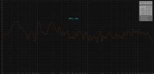
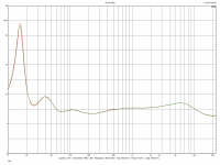
In addition, the measurement in the listening room. 2m, 2.5m. The listening position is 2.5m.
It puzzles me that from 2m and closer to the speakers (1m) I register a significant increase in energy in the 400-800Hz band. Maybe it's a reflection from the floor. In the listening position, it ceases to matter and even looks like the correct tonal balance.
Attachments
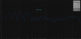
Wondering if something is not wired correctly, but I can't imagine that is the case?
Both speakers when measured about 3' from mic show a tremendous dip in energy in the mid bass. To confirm if this is audible, applying some EQ to the 1000-3000 range greatly changes how the system sounds. Brings out brass and organs much more as an example.
Now, if we have two speakers playing the same level from 1000 and under, and then the mids only play with half the number of drivers, this kinda makes sense. But I am not sure if we'd see that kind of energy drop. I am fairly certain this is not a room issue, as I see the same thing in all points of the room, and for both channels.
Would appreciate any insight on this, or if it is an issue at all, maybe reduced mids are intended.
Thanks!
They should be, unless the crossover was made wrong? Each woofer is wired in series, and then connect to the crossover as a whole. The bass/mid isn't really accurate since it connects to the xover board differently but yeah.Are the positive and negative of each speaker wired correctly, as per schematic?
Series, and then essentially in parallel?
I pulled the crossover, and it is set up correctly, Mid passes through L2 and then leaves, bass woofers go through the whole network and out. the two groups are wired in parallel.
Edit: I also did make sure that the tweeter has electrically negative into the positive terminal on the tweeter, so that is right.
Edit: I also did make sure that the tweeter has electrically negative into the positive terminal on the tweeter, so that is right.
Yeah I am at a loss for now.
I double checked the soldering on the woofers. For the top two, it is wired positive in, negative out to 2nd woofer's positive, negative out to negative ground. Same goes for bottom two. The top two are both wired to the mid portion of the crossover (just the inductor) and the bass the same way (to bass portion of xover)
Both speakers exhibit this behavior, and room effect isn't in play as either near field, mid field, far field, both or each all exhibit the dramatic dip.
Not sure what other troubleshooting steps I can go through for now. I can take any type of measurement needed.
The 1MH inductor crosses over at ~1300mhz which is where this dip is most dramatic, but I am not sure what is supposed to be picking up that energy? It isn't the tweeter, is it? Bass as far as I am aware drops off before that too.
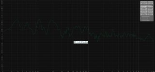
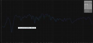
So I wish I could delete my posts above, since it seems like I am talking to myself. But I think I found the issue? Not sure how to correct though. Maybe this serves as a nice write up of trouble shooting though 😉.
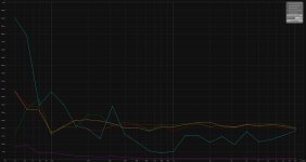
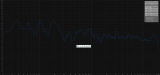
The only difference between the two below are about 2' of vertical distance. One where my head would be, one where my butt is. The green shows 0 loss of energy, where my butt would be. Blue shows complete loss of a lot.
Could my wave guide being 2mm recessed too far cause this @Joe Rasmussen ?
I think i'd like to ask about the great roll off after 10k, but could maybe just add some EQ if I want more there.

It really could be some weird room node canceling every bit of energy. Crazy to me it is so consistent no matter the mic position though.

The only difference between the two below are about 2' of vertical distance. One where my head would be, one where my butt is. The green shows 0 loss of energy, where my butt would be. Blue shows complete loss of a lot.
Could my wave guide being 2mm recessed too far cause this @Joe Rasmussen ?
I think i'd like to ask about the great roll off after 10k, but could maybe just add some EQ if I want more there.
It really could be some weird room node canceling every bit of energy. Crazy to me it is so consistent no matter the mic position though.
Last edited:
- Home
- Loudspeakers
- Multi-Way
- The "Elsinore Project" Thread