Please show your own measurements where they matter for us customers - for your product at 1 meter from the speaker.
//
//

Hello Joe, looks like I am really coming to an end with my new Elsinore Purify speakers. May be 1 or 2 weeks?
One questions occurs to me, you promote the transconductance amplifier for the Elsinores,
I have build the Pass F2J, in addition to this I think about your amplifier based on the chip amp. Do you have experienve about the best impedance for the Elsinores? Sorry, I didn't search both threats for this information. And, I don't like recommendations like "try till you have the best sound", I am looking for a starting point (something like the 15 ohm in parallel to your amplifier for 8 ohm speakers).
thanks in advance
Helmut
It's good for a cheap amp, the parts are cheap. But I am not sure if I would use it with the ULD version. But it is fun to build. The IC sounds better for it and I built it to prove that the Elsinores work with a current source amp with >200 Ohm o/put impedance.
I am fairly sure that the Pass F2J would surpass it though.
The Elsinores would work with an impedance up to infinity.

Green is voltage source and Red is current source. With the latter, the enormous power handling at LF will only be slightly less. I don't you will even notice it.
But what I am listening to looks something like this, where the EL34 output tubes only have 1.5x gain, so almost running the tubes at unity gain:

Bet you won't see a circuit like that every day. I would put this amp up against pretty much anything. The input converts voltage to current, which is the current that drives the Power Fet which is 'grounded' signal-wise (+35V). The non-linear Gate capacitance is suppressed because there is no signal on the gate, very wide bandwidth. I had somebody at Power Electronics in Segunda California (part of Tesla and SpaceX), computer model the circuit. It is phenomenally linear and low distortion and no feedback is required. I wish everybody here could hear this amp into a pair of Elsinores.
I am really forward to you finishing the ULD version.
I am fairly sure that the Pass F2J would surpass it though.
The Elsinores would work with an impedance up to infinity.
Green is voltage source and Red is current source. With the latter, the enormous power handling at LF will only be slightly less. I don't you will even notice it.
But what I am listening to looks something like this, where the EL34 output tubes only have 1.5x gain, so almost running the tubes at unity gain:
Bet you won't see a circuit like that every day. I would put this amp up against pretty much anything. The input converts voltage to current, which is the current that drives the Power Fet which is 'grounded' signal-wise (+35V). The non-linear Gate capacitance is suppressed because there is no signal on the gate, very wide bandwidth. I had somebody at Power Electronics in Segunda California (part of Tesla and SpaceX), computer model the circuit. It is phenomenally linear and low distortion and no feedback is required. I wish everybody here could hear this amp into a pair of Elsinores.
I am really forward to you finishing the ULD version.
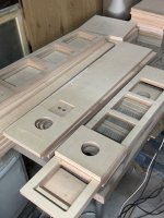
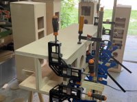
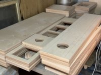
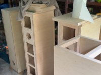
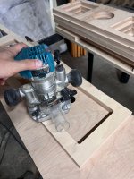
Many thanks for the quick reply. I struggled with my wood work because I intended to do it perfect. But I am no carpenter. Beech multiplex with a front made from Panzersperrholz. Nice contrast. The mistake was the glossy boat paint, nearly impossible for me to get a perfect surface.
Yes - I'm not so keen on dancing either. Will be just discrete nods from now on. Like the one above.You and I have done this dance before. No thanks.
//
Yes - I'm not so keen on dancing either. Will be just discrete nods from now on. Like the one above.
Hope you will understand that I will be publishing when ready and after a review by several other authorities, that everything holds water. It is not so much measurements of the Elsinores (although a possibility), but rather demonstrating why they are low distortion. So there will be distortion measurements.
As I said, you understand. It is not that I have entirely ignored your inquiry, that I can assure you. But the types of distortion I want to capture will involve LF frequencies (cone excursions) mixed with a midrange signal, which can be affected by the fact that the voice coil in not in the rest position. There are already others who are now doing this and it will become more common I am sure. But what I want to do is capture distortion on the current side of the amp and compare with the distortion on the voltage side. This will be revealing and I hope that might also become common. But we can only wait and see. BTW, I am not working entirely on my own, so self-deception is something I am aware of.
There are still some who think that all amplifiers, if operating correctly, basically sound the same. I am hoping to demonstrate a measurement that proves that we are not hearing the low distortion on the voltage side, but rather that a distortion mechanism that produces much higher distortion. If this is successful, then we may be able to say to the naysayers that we have a measurement that proves why amplifiers do sound different. If we can demonstrate something in the order of 20dB of distortion is involved, then the ultra-low distortions that are claimed are not quite what it seems.
I am putting a test jig together and a very carefully selected driver I have brought in as a reference, only for testing purposes. Basically it has to do with the inductance of the driver, it must be just right. You cannot use a resistive load, or dummy load for the tests in mind. This has to be a real driver with moving parts and a less than stable inductance. Measure the inductance at the rest position, then when the cone is pushed in about 4-5mm and the inductance goes up and when the cone is pushed out 4-5mm, the inductance goes down - we now know that this driver has a non-linear force factor. I have found a driver with just the right parameters (at least I hope, but I have done my homework).
Above is a good driver, but not Purifi. The inductance here at 0.0mm is about 0.11mH and that is too good, too low for what I need.
This is what I have acquired and it looks just right.
Vifa P17WJ08
Three positions, there are different values of inductance.
Rest:
In:
Out:
But since current is proportional to the load...? Here current of the amplifier is being modulated and when LF/Mid signals are processed, then distortion will show up in the midrange, both on the electrical side (current) and the acoustic side (microphone). And there should be an obvious correlation between the two.
The measurement jig I will be using:
So you will get an idea that some preparations have to be made and I am getting close to where I need to be.
I use a ClioFW01 analyser, 24bit/192K audio analyser. but I have acquired a 32bit analyser from Quant Asylum, the QA 403.
https://quantasylum.com/products/qa403-audio-analyzer
I was lucky to get one of these. with the shortage of chips etc. Got in early and paid on the dot. A few basic tests and it is a fair bit better than my Clio 24 bit. But the downloadable free software is on so-so. It has no real IMD calculation function. I have asked... but they keep promising.
It would be great if REW worked with it. Then I would definitely be using REW and learning the ropes.
Midnight here...
To me it seems you are over thinking it.. if you can measure acoustical distorsion, it would suffice I suppose.
//
//
Having measurements of the speaker, with Zobel against the same speaker without, would go a long way.
But what it seems is that you are using many words to claim that flattening impedance curves reduces distortion by presenting the amp with an easier load to drive.
But what it seems is that you are using many words to claim that flattening impedance curves reduces distortion by presenting the amp with an easier load to drive.
Sure, it is an easier load to drive. But more than that is involved.
Take a close look at those inductance measurements above. An unstable inductance as shown in post #4807 and we see a variation in inductance by 19.5% and what does that mean? Let us round that out to 20%.
THAT 20% INDICATES MASSIVE CHANGES IN FORCE FACTOR (BL) WHEN LOW FREQUENCY AND HARMONICS PLUS MIDRANGE ARE MIXED!
20%!!!
THIS IS ABOUT FORCE FACTOR BL DISTORTION!
And the force factor is directly related to the current coming from the amplifier.
Sorry if the above comes across as a bit shouty, I apologise.
If you want to hear an example, go to this blog post:
https://purifi-audio.com/2019/12/07/amfm
Note that AM, amplitude modulated, distortion is caused by the force factor and known as BL, as it changes with a 43 Hertz modulation (physical excursion of the driver) and 1Khz.
My point is that this unstable BL modulates the current in a voltage source in a way that it can not in a current source. So essentially we hear more distortion when using a voltage source when compared to a current source.
Hence we are not talking about easy loads or enough current headroom.
A current source can have as much as 20dB advantage in distortion and that is why we see it in active loudspeakers, and you can buy these right now. But what about the rest of us?
In the Elsinores, two techniques are employed:
1) Equalise, EQ the current of the amplifier to mirror the speaker. This stabilises the current in the voice coil and that seen by the amplifier.
2) Use as large as possible external series inductance to suppress the 20% inductance variation. The total inductance is smoothed out, the current is more stable. The external inductor does not change with BL changes.

The BL is modulated by Part B of the impdance at low frequencies when excursions occur. Parallel current (EQ) will stabilise Part B and so will a series inductor. Current, BL and force factor, they are related and controlling them leads to lower distortion.
Combine an LF signal like 40 Hertz to modulate (sample) the cone whilst some mid-tones are also played, with the above two techniques you will get a reduction in distortion.
So it isn't just about easy loads or the amplifier having enough current. It is about stabilising the force factor (BL) that we normally see with current sources. The advantage of the so-called current-drive is more linear (but not perfect) BL and that results in lower distortion. But the driver needs to be carefully chosen.
We also need to get away from the classical view that there is no break between voltage and current. The view is that the voltage across the driver terminals always will equate to a defined amount of current. But there are mechanisms that prevent that classical view to be entirely true. If up to 20% variations of inductance (inductance is usually relative to BL), then a percentage of change in many percent is inescapable, and that is distortion.
Some active speaker uses current drive, but not on the bass:

https://www.soundonsound.com/reviews/kii-audio-three

https://www.sgraudio.com/sgr-audio-...its-cx3b-mk1-and-cx3c-mk1-active-loudspeakers
Final note: Nobody has done current drive in the bass.
Or have they? Look closely at the Elsinores, they show how it can be done. Most designers don't think it is possible. But if we follow what the current does, the damping, or Q, of a system, can also be defined by current-versus-frequency. Control the current as it changes frequency and you can control the Q with a current source. Beyond that, for now, I am going to stay silent. 😉 But I will publish it.
Take a close look at those inductance measurements above. An unstable inductance as shown in post #4807 and we see a variation in inductance by 19.5% and what does that mean? Let us round that out to 20%.
THAT 20% INDICATES MASSIVE CHANGES IN FORCE FACTOR (BL) WHEN LOW FREQUENCY AND HARMONICS PLUS MIDRANGE ARE MIXED!
20%!!!
THIS IS ABOUT FORCE FACTOR BL DISTORTION!
And the force factor is directly related to the current coming from the amplifier.
Sorry if the above comes across as a bit shouty, I apologise.
If you want to hear an example, go to this blog post:
https://purifi-audio.com/2019/12/07/amfm
Note that AM, amplitude modulated, distortion is caused by the force factor and known as BL, as it changes with a 43 Hertz modulation (physical excursion of the driver) and 1Khz.
My point is that this unstable BL modulates the current in a voltage source in a way that it can not in a current source. So essentially we hear more distortion when using a voltage source when compared to a current source.
Hence we are not talking about easy loads or enough current headroom.
A current source can have as much as 20dB advantage in distortion and that is why we see it in active loudspeakers, and you can buy these right now. But what about the rest of us?
In the Elsinores, two techniques are employed:
1) Equalise, EQ the current of the amplifier to mirror the speaker. This stabilises the current in the voice coil and that seen by the amplifier.
2) Use as large as possible external series inductance to suppress the 20% inductance variation. The total inductance is smoothed out, the current is more stable. The external inductor does not change with BL changes.
The BL is modulated by Part B of the impdance at low frequencies when excursions occur. Parallel current (EQ) will stabilise Part B and so will a series inductor. Current, BL and force factor, they are related and controlling them leads to lower distortion.
Combine an LF signal like 40 Hertz to modulate (sample) the cone whilst some mid-tones are also played, with the above two techniques you will get a reduction in distortion.
So it isn't just about easy loads or the amplifier having enough current. It is about stabilising the force factor (BL) that we normally see with current sources. The advantage of the so-called current-drive is more linear (but not perfect) BL and that results in lower distortion. But the driver needs to be carefully chosen.
We also need to get away from the classical view that there is no break between voltage and current. The view is that the voltage across the driver terminals always will equate to a defined amount of current. But there are mechanisms that prevent that classical view to be entirely true. If up to 20% variations of inductance (inductance is usually relative to BL), then a percentage of change in many percent is inescapable, and that is distortion.
Some active speaker uses current drive, but not on the bass:
https://www.sgraudio.com/sgr-audio-...its-cx3b-mk1-and-cx3c-mk1-active-loudspeakers
Final note: Nobody has done current drive in the bass.
Or have they? Look closely at the Elsinores, they show how it can be done. Most designers don't think it is possible. But if we follow what the current does, the damping, or Q, of a system, can also be defined by current-versus-frequency. Control the current as it changes frequency and you can control the Q with a current source. Beyond that, for now, I am going to stay silent. 😉 But I will publish it.
Sure, it is an easier load to drive. But more than that is involved.
Take a close look at those inductance measurements above. An unstable inductance as shown in post #4807 and we see a variation in inductance by 19.5% and what does that mean? Let us round that out to 20%.
THAT 20% INDICATES MASSIVE CHANGES IN FORCE FACTOR (BL) WHEN LOW FREQUENCY AND HARMONICS PLUS MIDRANGE ARE MIXED!
20%!!!
THIS IS ABOUT FORCE FACTOR BL DISTORTION!
And the force factor is directly related to the current coming from the amplifier.
Sorry if the above comes across as a bit shouty, I apologise.
If you want to hear an example, go to this blog post:
https://purifi-audio.com/2019/12/07/amfm
Note that AM, amplitude modulated, distortion is caused by the force factor and known as BL, as it changes with a 43 Hertz modulation (physical excursion of the driver) and 1Khz.
My point is that this unstable BL modulates the current in a voltage source in a way that it can not in a current source. So essentially we hear more distortion when using a voltage source when compared to a current source.
Hence we are not talking about easy loads or enough current headroom.
A current source can have as much as 20dB advantage in distortion and that is why we see it in active loudspeakers, and you can buy these right now. But what about the rest of us?
In the Elsinores, two techniques are employed:
1) Equalise, EQ the current of the amplifier to mirror the speaker. This stabilises the current in the voice coil and that seen by the amplifier.
2) Use as large as possible external series inductance to suppress the 20% inductance variation. The total inductance is smoothed out, the current is more stable. The external inductor does not change with BL changes.
View attachment 1079823
The BL is modulated by Part B of the impdance at low frequencies when excursions occur. Parallel current (EQ) will stabilise Part B and so will a series inductor. Current, BL and force factor, they are related and controlling them leads to lower distortion.
Combine an LF signal like 40 Hertz to modulate (sample) the cone whilst some mid-tones are also played, with the above two techniques you will get a reduction in distortion.
So it isn't just about easy loads or the amplifier having enough current. It is about stabilising the force factor (BL) that we normally see with current sources. The advantage of the so-called current-drive is more linear (but not perfect) BL and that results in lower distortion. But the driver needs to be carefully chosen.
We also need to get away from the classical view that there is no break between voltage and current. The view is that the voltage across the driver terminals always will equate to a defined amount of current. But there are mechanisms that prevent that classical view to be entirely true. If up to 20% variations of inductance (inductance is usually relative to BL), then a percentage of change in many percent is inescapable, and that is distortion.
Some active speaker uses current drive, but not on the bass:
https://www.soundonsound.com/reviews/kii-audio-three
https://www.sgraudio.com/sgr-audio-...its-cx3b-mk1-and-cx3c-mk1-active-loudspeakers
Final note: Nobody has done current drive in the bass.
Or have they? Look closely at the Elsinores, they show how it can be done. Most designers don't think it is possible. But if we follow what the current does, the damping, or Q, of a system, can also be defined by current-versus-frequency. Control the current as it changes frequency and you can control the Q with a current source. Beyond that, for now, I am going to stay silent. 😉 But I will publish it.
Hello Joe,
I have to agree that voltage source and current source amplifiers are different.
Voltage source amps have a fixed “regulated” voltage gain; 1 volt in, 10 volts out or something like that.
Current source amps have a fixed “regulated” voltage input to current output gain; 1 volt in, 2 amps out or something like that. Not much is said about the voltage output of current source amps. Interesting, as the load impedance increases the output voltage increases in a predictable proportionate amount to maintain the current output. Perhaps due to fuzzy load impedance we can call this voltage distortion.
While you are sorting out your testing protocols perhaps you can also input the current source amplifier output voltage into one of the inputs on your analyzer and run an additional FFT, multi-tone or IMD measurement.
I like the direction that you are going with the new reference 17WJ008 Vifa driver to test and illustrate distortion. It is a real honest mainstream driver that does not have all the advanced distortion reduction features that are designed and built into the Purifi Drivers.
Thanks DT
I have to agree that voltage source and current source amplifiers are different.
Good.
Voltage source amps have a fixed “regulated” voltage gain; 1 volt in, 10 volts out or something like that.
Correct.
Current source amps have a fixed “regulated” voltage input to current output gain; 1 volt in, 2 amps out or something like that. Not much is said about the voltage output of current source amps. Interesting, as the load impedance increases the output voltage increases in a predictable proportionate amount to maintain the current output. Perhaps due to fuzzy load impedance we can call this voltage distortion.
If you go back, you will notice that I have covered this.
The interesting thing is that this 'voltage' is still there, even when the amp is a voltage source. I know this is hard to grasp, but that voltage is always there.
I even supplied the maths:
At 3KHz you get 9dB less output with a voltage source compared to a current source. That voltage now shows up inside the driver's impedance as Part B of the overall impedance:
Note the "V".
At 3KHz the Part B of the impedance is actually inductive-EMF which shows up as a voltage. As such the voltage/impedance now reduces the current relative to the full current of the current source.
I still remember the day that this dawned on me. I did the measurements, I also modeled it and developed the above maths. I then presented it to somebody that worked as both designer and scientist for a major Scottish company (you may guess) and he said he could not fault it.
Again, take a look below:
Standard graph of a driver that I have right here. Did the measurement. Note the bottom light green area. This is the DC resistance of the driver, the Re = 6 Ohm. All the above calculation and the difference between when this driver is both current source driven versus voltage source driven.
Any impedance above Re = 6R is some form of EMF, electromotive force, both in Ohm and in voltage. The impedance rise above Re is a force as in EMF, the F stands for force is always a voltage!
Yes, EMF, is a voltage.
This is back-EMF and it opposes the current and hence acts as an impedance.
Both a voltage and an impedance at the same time?
Pointing this out elsewhere got me into a lot of trouble and ridicule. But I went to people who know their stuff and pointed it out and they had no problem with it.
BUT...
When we use a current source, that EMF does not act as an impedance. Yeah, it does not impede the current. The voltage still shows up, but it will not oppose the current. It will no longer act as an impedance. Hence in the comparison graph above, the output with a current source is always higher than a voltage source.
The difference in SPL output in dB is directly related only to the current!
The maths I presented proves it down to 1mA resolution and I can better that if I tried. It just works!
I wonder if you can see and grasp the above. It is not easy. But it is logical.
It took me a while to do just that, but then Menno Vanderveen said that "thinking current is hard" and it is. Have you ever seen a negative of a print? It's hard to make things out because everything is reversed. The same thing when thinking about current, often it is the opposite to what we would normally think. Voltage is familiar English and current is more like Chinese.
About the Vifa driver, yes you are absolutely spot on about the qualities it has and why I do believe it is a good choice. And yes you are right, my current source amplifier will definitely be used in the protocols that are being devised.
The worst that can happen is that I fail. 😳
But seriously, some measurements have already been done and these are already in line with where we are going. So that is confidence building. Also that this is very much science-based and I have several scientist friends looking over my shoulder - so we are not examining some magic pudding, right? 😎
Cheers, Joe
Good.
Correct.
If you go back, you will notice that I have covered this.
The interesting thing is that this 'voltage' is still there, even when the amp is a voltage source. I know this is hard to grasp, but that voltage is always there.
View attachment 1079897
I even supplied the maths:
View attachment 1079898
At 3KHz you get 9dB less output with a voltage source compared to a current source. That voltage now shows up inside the driver's impedance as Part B of the overall impedance:
View attachment 1079899
Note the "V".
At 3KHz the Part B of the impedance is actually inductive-EMF which shows up as a voltage. As such the voltage/impedance now reduces the current relative to the full current of the current source.
I still remember the day that this dawned on me. I did the measurements, I also modeled it and developed the above maths. I then presented it to somebody that worked as both designer and scientist for a major Scottish company (you may guess) and he said he could not fault it.
Again, take a look below:
View attachment 1079900
Standard graph of a driver that I have right here. Did the measurement. Note the bottom light green area. This is the DC resistance of the driver, the Re = 6 Ohm. All the above calculation and the difference between when this driver is both current source driven versus voltage source driven.
Any impedance above Re = 6R is some form of EMF, electromotive force, both in Ohm and in voltage. The impedance rise above Re is a force as in EMF, the F stands for force is always a voltage!
Yes, EMF, is a voltage.
This is back-EMF and it opposes the current and hence acts as an impedance.
Both a voltage and an impedance at the same time?
Pointing this out elsewhere got me into a lot of trouble and ridicule. But I went to people who know their stuff and pointed it out and they had no problem with it.
BUT...
When we use a current source, that EMF does not act as an impedance. Yeah, it does not impede the current. The voltage still shows up, but it will not oppose the current. It will no longer act as an impedance. Hence in the comparison graph above, the output with a current source is always higher than a voltage source.
The difference in SPL output in dB is directly related only to the current!
The maths I presented proves it down to 1mA resolution and I can better that if I tried. It just works!
I wonder if you can see and grasp the above. It is not easy. But it is logical.
It took me a while to do just that, but then Menno Vanderveen said that "thinking current is hard" and it is. Have you ever seen a negative of a print? It's hard to make things out because everything is reversed. The same thing when thinking about current, often it is the opposite to what we would normally think. Voltage is familiar English and current is more like Chinese.
About the Vifa driver, yes you are absolutely spot on about the qualities it has and why I do believe it is a good choice. And yes you are right, my current source amplifier will definitely be used in the protocols that are being devised.
The worst that can happen is that I fail. 😳
But seriously, some measurements have already been done and these are already in line with where we are going. So that is confidence building. Also that this is very much science-based and I have several scientist friends looking over my shoulder - so we are not examining some magic pudding, right? 😎
Cheers, Joe
Hello Joe,
Some of this stuff above is a bit fuzzy.
The figure below shows a voltage divider. The current source amplifier voltage output is divided across both impedance Part A and impedance Part B.
The current source amplifier maintains its' current output by increasing its' output voltage to compensate for the voltage drop across Part B of the voltage divider shown below. The current remains constant. The Voltage increases.
This is part of the secret putting.
"The difference in SPL output in dB is directly related only to the current!"
This is clearly not correct. SPL output is a function of Watts. Electrical Watts are equal to Volts X Amps.
Current source amplifiers modulate the output voltage to hold the current gain constant. With the current gain held constant it is modulated voltage that that is responsible for changed SPL output. (This is just a few raisins added to the secret putting.)
Please include variable output Volts in the modeling and discussion of current source amplifiers.
Thanks DT
Last edited:
it’s the current that produces a force out of the motor Bl(x, i, t) • i(t). Watts is irrelevant
it’s the current that produces a force out of the motor Bl(x, i, t) • i(t). Watts is irrelevant
Hello,
Only partial credit for you.
Oh yes, it is Watts that do the work, no Watts, no current and no SPL.
Remember that in the current source amplifier current gain is constant and that it is voltage modulation that makes that possible.
Thanks DT
work/Watts is relevant for the electricity bill but force is what makes the sound
Still only partial credit.
Yes current makes force in the motor. This part is correct.
Without Volts there is no Current.
Volts X current X motor efficiency is equal to acoustic Watts output.
It still is Watts that do the work.
Thanks DT
It depends what we label distortion, right? The current source amplifier results in more frequency response distortion. That driver's frequency response is optimized for flattest frequency response with constant voltage.Good.
Correct.
If you go back, you will notice that I have covered this.
The interesting thing is that this 'voltage' is still there, even when the amp is a voltage source. I know this is hard to grasp, but that voltage is always there.
View attachment 1079897
I even supplied the maths:
View attachment 1079898
At 3KHz you get 9dB less output with a voltage source compared to a current source. That voltage now shows up inside the driver's impedance as Part B of the overall impedance:
View attachment 1079899
Note the "V".
At 3KHz the Part B of the impedance is actually inductive-EMF which shows up as a voltage. As such the voltage/impedance now reduces the current relative to the full current of the current source.
I still remember the day that this dawned on me. I did the measurements, I also modeled it and developed the above maths. I then presented it to somebody that worked as both designer and scientist for a major Scottish company (you may guess) and he said he could not fault it.
Again, take a look below:
View attachment 1079900
Standard graph of a driver that I have right here. Did the measurement. Note the bottom light green area. This is the DC resistance of the driver, the Re = 6 Ohm. All the above calculation and the difference between when this driver is both current source driven versus voltage source driven.
Any impedance above Re = 6R is some form of EMF, electromotive force, both in Ohm and in voltage. The impedance rise above Re is a force as in EMF, the F stands for force is always a voltage!
Yes, EMF, is a voltage.
This is back-EMF and it opposes the current and hence acts as an impedance.
Both a voltage and an impedance at the same time?
Pointing this out elsewhere got me into a lot of trouble and ridicule. But I went to people who know their stuff and pointed it out and they had no problem with it.
BUT...
When we use a current source, that EMF does not act as an impedance. Yeah, it does not impede the current. The voltage still shows up, but it will not oppose the current. It will no longer act as an impedance. Hence in the comparison graph above, the output with a current source is always higher than a voltage source.
The difference in SPL output in dB is directly related only to the current!
The maths I presented proves it down to 1mA resolution and I can better that if I tried. It just works!
I wonder if you can see and grasp the above. It is not easy. But it is logical.
It took me a while to do just that, but then Menno Vanderveen said that "thinking current is hard" and it is. Have you ever seen a negative of a print? It's hard to make things out because everything is reversed. The same thing when thinking about current, often it is the opposite to what we would normally think. Voltage is familiar English and current is more like Chinese.
About the Vifa driver, yes you are absolutely spot on about the qualities it has and why I do believe it is a good choice. And yes you are right, my current source amplifier will definitely be used in the protocols that are being devised.
The worst that can happen is that I fail. 😳
But seriously, some measurements have already been done and these are already in line with where we are going. So that is confidence building. Also that this is very much science-based and I have several scientist friends looking over my shoulder - so we are not examining some magic pudding, right? 😎
Cheers, Joe
sure but the far majority of watts get burned as heat in the motor without doing any work at all. If one want to study distortion as we care about in this discussion then the Lorentz force of the coil is the quantity to study. Controlling the current and keeping Bl constant is key in order to reduce distortion as Joe has been teaching Thanks, LarsStill only partial credit.
Yes current makes force in the motor. This part is correct.
Without Volts there is no Current.
Volts X current X motor efficiency is equal to acoustic Watts output.
It still is Watts that do the work.
Thanks DT
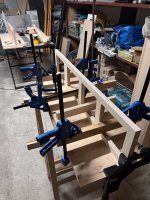
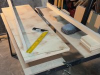
I did not expect this. Four pairs of crates for gluing landed in my tiny garage. I'm trying to control this chaos 🙂. Keep fingers crossed.
Attachments
-
 IMG_1568.jpeg386.9 KB · Views: 158
 -
 IMG_1567.jpeg333.2 KB · Views: 147
 -
 68185249837__68BF2487-3F51-4592-A2EA-4CD28450DB7F.jpeg522.4 KB · Views: 144
 -
 IMG_1564.jpeg377.7 KB · Views: 144
 -
 IMG_1563.jpeg371.1 KB · Views: 155
 -
 IMG_1562.jpeg318.3 KB · Views: 152
 -
 IMG_1561.jpeg305.3 KB · Views: 150
 -
 68174897610__C091BD81-204C-458A-9207-EB5C307AC345.jpeg466.7 KB · Views: 151
- Home
- Loudspeakers
- Multi-Way
- The "Elsinore Project" Thread