I find the Purifi articles fascinating and the voltage vs current drive also interesting. Some of the challenges of controlling drivers seems to be overcoming X displacement issues. The Purifi drivers seemed to be aimed at getting the most out of a relatively compact 2 way and hence have targeted high Xmax with low distortion. The Elsinores achieve this with extra Sd with 4 drive units per speaker. Another approach to get low distortion in the 300Hz to 2khz band (as mentioned in the Purifi article) is to go 3 way. Taking the Elsinores as an example, the top 2 drives could be crossed at 300 Hz to the bottom 2 . The top 2 would then have greatly reduced displacement and could also maybe use slightly small drivers to better integrate to the tweeters and the bottom 2 could use bigger drivers to increase Sd and have lower Fs. The midranges would require less volume which could then be used for the woofers. Of course this would be a completely different speaker but my point is that a midrange in a 3 way would mitigate the distortion in the 300 to 2k Hz band.
It is not so much an issue of displacement as non-linear excursion causing AM distortion.
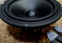
I have a classic Vifa P17WJ08 driver and it has become a standard to me, a kind of starting point.

You can see the probes attached, this goes to an LCR meter.
This is the inductance of the driver with the cone in the neutral resting position:

Now gently push the cone in about 4mm, the is known as the negative (-) position:

The inductance rises.
Now gently pull out the come by 4mm and this is the positive (+) position:

Quite a drop, getting near 20% here.
What is certain here is that the inductance changes with excursion and that the implications are two-fold.
1. The amplifier is affected on the current side as we will witness "impedance modulations" of the impedance of the driver, which is clearly not stable with excursions. It is interesting that when I referred to "impedance modulations" in the past years, I was trolled. But now we have Purifi's Lars Risbo also referring to "impedance modulations" and when I pointed out that it was the current of the amplifier that was modulated, he agreed. I added that this was also an indication that we never listen directly to the voltage of the amplifier, the voltage only creates a potential for current which can be corrupted by poor drivers and that will never be a substitute for the quality of the driver. Not surprising that he agreed here as well.
2. Since there is a relationship between the inductance and force factor BL it is clear that this will cause AM distortion when an LF signal like 40 Hertz (let us say -/+4mm) and a 1KHz tone, that the higher tone(s) in the critical midrange is going to be impacted, not the LF so much, where we are much less sensitive to distortion. This is actually Purifi's argument and anybody wanting to look into it some more, read Purifi's logs:
Distortion, The Sound That Dare Not Speak Its Name
Some Speaker Problems That Needed Solving.
Low-frequency harmonic distortion is almost inaudible.
Doppler distortion vs IMD?
So we have BL modulations, and since BL is the force-factor, they have called it Force-Factor Modulations (FFM) and we also have Impedance Modulations and both impact the amplifier on the current side. If you hear a speaker distort, then you are modulating the current of the amplifier and hence you are now listening to this dance between the loudspeaker and the amplifier. Honestly, this area is yet to be really looked at (I am trying).
EDIT:
This is the curve that shows changes of inductance versus position:

The above is good, here is a worse example, much higher inductance:

This is what Purifi has accomplished:

I have a classic Vifa P17WJ08 driver and it has become a standard to me, a kind of starting point.
You can see the probes attached, this goes to an LCR meter.
This is the inductance of the driver with the cone in the neutral resting position:
Now gently push the cone in about 4mm, the is known as the negative (-) position:
The inductance rises.
Now gently pull out the come by 4mm and this is the positive (+) position:
Quite a drop, getting near 20% here.
What is certain here is that the inductance changes with excursion and that the implications are two-fold.
1. The amplifier is affected on the current side as we will witness "impedance modulations" of the impedance of the driver, which is clearly not stable with excursions. It is interesting that when I referred to "impedance modulations" in the past years, I was trolled. But now we have Purifi's Lars Risbo also referring to "impedance modulations" and when I pointed out that it was the current of the amplifier that was modulated, he agreed. I added that this was also an indication that we never listen directly to the voltage of the amplifier, the voltage only creates a potential for current which can be corrupted by poor drivers and that will never be a substitute for the quality of the driver. Not surprising that he agreed here as well.
2. Since there is a relationship between the inductance and force factor BL it is clear that this will cause AM distortion when an LF signal like 40 Hertz (let us say -/+4mm) and a 1KHz tone, that the higher tone(s) in the critical midrange is going to be impacted, not the LF so much, where we are much less sensitive to distortion. This is actually Purifi's argument and anybody wanting to look into it some more, read Purifi's logs:
Distortion, The Sound That Dare Not Speak Its Name
Some Speaker Problems That Needed Solving.
Low-frequency harmonic distortion is almost inaudible.
Doppler distortion vs IMD?
So we have BL modulations, and since BL is the force-factor, they have called it Force-Factor Modulations (FFM) and we also have Impedance Modulations and both impact the amplifier on the current side. If you hear a speaker distort, then you are modulating the current of the amplifier and hence you are now listening to this dance between the loudspeaker and the amplifier. Honestly, this area is yet to be really looked at (I am trying).
EDIT:
This is the curve that shows changes of inductance versus position:
The above is good, here is a worse example, much higher inductance:
This is what Purifi has accomplished:
Attachments
Last edited:
Here are the Purifi boxes on their way to being made. Thanks to Rhys of www.frontleftspeaker.com for taking this on at such a crazy time. Since we also have summer holidays, everybody is closing down and most that I know are coming back Monday 17th January.

Rhys has changed the cutting plan so that the front panel becomes a single piece, with no actual joins to be seen there.
This is what he came up with:

Rhys has changed the cutting plan so that the front panel becomes a single piece, with no actual joins to be seen there.
This is what he came up with:
Last edited:
Looks nice! thanks for the neat explanation.
In the shop pics, I see what looks to be parts for another Elsinore speaker. Are you doing more than two? I like the small roundover detail on the baffle. Looks like a 1" round over just with the depth set very high.
What is the 330x440 piece used for?
In the shop pics, I see what looks to be parts for another Elsinore speaker. Are you doing more than two? I like the small roundover detail on the baffle. Looks like a 1" round over just with the depth set very high.
What is the 330x440 piece used for?
So is the value Le a quick indicator of a good driver with lower being better in the above scenario or is it more to do with the change in Le with lower being better?
If its a change in Le then the 'better' example from the graphs above has a change from approx. 0.115mH to 0.15mH with -5mm displacement which is about a 0.035mH change which is approx a 30% change relative to the starting position.
The 'worse' example above is about 0.88mH to 1mH for -5mm displacement which is approx 0.12mH change which about 14% relative to the starting inductance.
I'm guessing the lower actual inductance is better as 0.115mH is 0.58 ohms at 800Hz (to use the freq used in the LCR meter above) whereas 0.88mH has a reactance of 4.4 ohms. So if these are effectively in series with the dc resistance of the coil then the lower inductive coil will be less significant to the overall impedance. So the lower Le driver would have a 0.75 ohm - 0.58 ohm = 0.17 ohm change whereas the high Le driver would change 5 - 4.4 ohm = 0.6 ohm (at 800Hz). I hope my reasoning is not a million miles off.
Hi Stal
No, your reasoning is not a million miles off.
This is indeed a tricky subject, but generally, a low Le inductance is a good thing. Here the SB17 driver we have used is exceptionally low. The Purifi is about double at mid-frequencies and three times at 10KHz. So the SB17 wins hands down, right? Not so simple, here the Purifi is still considered low inductance (just not as low) and here they have concentrated on it being stable with excursions up to Xmax. In other words, it is the stability of the Le that is important. Their inductance is linked with a more stable force factor. So whether the cone goes in or whether out, the force factor does not change, hardly. This reduces AM (amplitude modulated) distortion, which they consider more important than FM (frequency modulated) distortion (example here is Doppler).
The reduction in distortion is what is important and they, Purifi, know that current-drive can have 15dB or more reduction in distortion because under current-drive the current is fixed and hence the force-factor will be more linear with respect to excursions (because the amplifier lock in the current). They want that same reduction in distortion, knowing that their speakers are going to be connected to voltage sources. Both current sources and voltage sources have pros and cons, but voltage sources will always rule, so Purifi wants us still to have that reduction in distortion with voltage sources.
There is no doubt that the Re DC series resistance of the voice coil has a stabilising influence as well. It is indeed in series and stable part of the over impdance (some thermal effects, but they rarely show up at audio frequencies, only very low LF, according to Earl Geddes).
But we seem to be getting into an age where more of an effort is being made to understand this. While I have areas where I don't agree with his conclusions, Esa Merilain's book on Current-Drive in 2010 (when I got my copy early) may prove to be a landmark - in the last ten years, there has been "movement at the station" to quote Australian bush poet Banjo Paterson.
In the shop pics, I see what looks to be parts for another Elsinore speaker. Are you doing more than two? I like the small roundover detail on the baffle... Looks like a 1" round over just with the depth set very high.
What is the 330x440 piece used for?
He is doing two pairs, one Purifi "ULD" pair and the other the current EL-6 which will be fitted with SB17MFC35-8 drivers. But the Purifi will get the focus, the others later on. More economic to make two pairs.
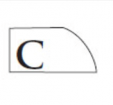
The round over is 5mm radius (10mm diameter), maybe looks bigger than it is?
The 330x400 will be under the regular box, increasing the surface area on the floor for stability.
Hi Allen
No, linearity, as being linear, meaning a straight line:
Dictionary: "...arranged in or extending along a straight or nearly straight line. "linear movement""
Linear as in this, straight lines, below:

Flat lines!
The key here is that non-straight lines create distortion. But I was simply talking about Le as being linear with cone excursion.
My understanding, it is interesting to note that Purifi looks like they wrote their own software and used Klippel (I am assuming) hardware. I think that they are hoping that this kind of measurement will also be published for other drivers. We can only hope.
No, linearity, as being linear, meaning a straight line:
Dictionary: "...arranged in or extending along a straight or nearly straight line. "linear movement""
Linear as in this, straight lines, below:
Flat lines!
The key here is that non-straight lines create distortion. But I was simply talking about Le as being linear with cone excursion.
My understanding, it is interesting to note that Purifi looks like they wrote their own software and used Klippel (I am assuming) hardware. I think that they are hoping that this kind of measurement will also be published for other drivers. We can only hope.
Joe, you are correct. By keeping L(x) constant (flat lines on the graph) then booth FFM and impedance/current modulation is avoided. We built our own hardware (Røde Boks) and analyser software for it. How to measure L at all frequencies and positions was a tough problem to solve. Its verified against static measurements where the coil is positioned using a step motor. These L(x,f) graphs are like an x ray of the motor. show me the curves and I can tell how the motor is constructed.
metre Xmax,
Lars
metre Xmax,
Lars
Thanks Lars, good to see you making an appearance here. I was the one that made that comment about impedance/current modulations on your YouTube video with Erin. Interesting that you did the hardware side as well, hadn't guessed that, impressive!
Cheers, Joe
Cheers, Joe
Hey Joe,Here are the Purifi boxes on their way to being made. Thanks to Rhys of www.frontleftspeaker.com for taking this on at such a crazy time. Since we also have summer holidays, everybody is closing down and most that I know are coming back Monday 17th January.
View attachment 1008186
Rhys has changed the cutting plan so that the front panel becomes a single piece, with no actual joins to be seen there.
This is what he came up with:
View attachment 1008187
I would like to use this box layout for my Elsanores with the SB 17MFC35-8 drivers. Using my limited math skills, it looks like the box volume is the same as the existing plans for the Mk6 -- only difference I see is the Purifi box driver hole size is 178mm/146mm and the Mk 6 box size is 174mm/146mm.
I like the idea of being able to round over the front panel and have the seams on the side vice the front of the box. I'm about to start cutting and gluing up my MDF panels (using 1/2" MDF -- white foam 2" insulation panel is going to be my cutting surface so I can cut the MDF on the floor and not have to try to lift the full size panels onto my table saw) -- any issues in shifting to this layout as supplied by FrontLeftSpeaker for my Mk 6's??
Thanks,
HappyJack
Attachments

I just opened up my Mk6 waveguides from Joe, and just wanted to note, and thank him, for including all the fasteners necessary to install them.
Thank you!
Thank you!
If you're going to round over, maybe you could try dadoing the side panels into the front to where the rounder starts (adjusting the side panel size as necessary. You are using half inch so you could get creative. That may help camouflage the end grain of the MDF once it does the inevitable end grain pop thing that it does.I like the idea of being able to round over the front panel and have the seams on the side vice the front of the box.
... it looks like the box volume is the same as the existing plans for the Mk6 -- only difference I see is the Purifi box driver hole size is 178mm/146mm and the Mk 6 box size is 174mm/146mm.
I like the idea of being able to round over the front panel and have the seams on the side vice the front of the box....
Hi Happy (always wanted to say that to somebody... 🙂)
1. Yes, the box is the same, the port tuning will be different, but is 100mm long with SB17MFC-08 driver.
Please note that the driver insertion is 7mm for the current design, so 174mm/146mm/7mm is what you will be using.
2. Yes, the drawing I posted from Rhys shows an alternative way to do the front panel, so now constructors can choose what they prefer. I like the idea that there will be no joins shown looking at the front of the speaker.
Again, thanks to Rhys.
That's what I just did. Totally makes sense to me. I'm using bamboo ply though. Solid end grain.If you're going to round over, maybe you could try dadoing the side panels into the front to where the rounder starts (adjusting the side panel size as necessary. You are using half inch so you could get creative. That may help camouflage the end grain of the MDF once it does the inevitable end grain pop thing that it does.
Attachments
perceptionchanges,
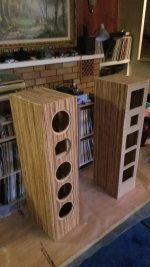
Those cabinets are looking very nice.
If I am not wrong, the internal baffle is made of MDF? Did you use MDF for the internal bracing and 3/4" bamboo ply for the front, sides, top and back?
Those cabinets are looking very nice.
If I am not wrong, the internal baffle is made of MDF? Did you use MDF for the internal bracing and 3/4" bamboo ply for the front, sides, top and back?
perceptionchanges,
Those cabinets are looking very nice.
If I am not wrong, the internal baffle is made of MDF? Did you use MDF for the internal bracing and 3/4" bamboo ply for the front, sides, top and back.
More or less, I used mdf for the back too, with a laminate as a finish. All internal is mdf, except the secondary tweeter panel, which are off cuts of the bamboo.
- Home
- Loudspeakers
- Multi-Way
- The "Elsinore Project" Thread