I am building a new F6 with IRFP240s (the earlier one was a semisouth based). I realize that I don't have 18 ohms resistors and cannot get easily in the market. I do have 22 ohms, 1% dales. Can they be used instead of 18 ohms in the circuit?
There are no critical values in this or probably any of my DIY designs.
Just see to it that you use the same values for both channels. 😛
My understanding is the B1 has a touch of K2 and it could be that is the reason I like the F6 with the B1.
The latest (DC coupled) B1's second harmonic is the result of the slightly
higher transconductance of the P channel JFET. In the earlier version it is
simply the result of the single-ended operation.
The latest (DC coupled) B1's second harmonic is the result of the slightly
higher transconductance of the P channel JFET. In the earlier version it is
simply the result of the single-ended operation.
Hi Mr. Pass,
Would that be similar to the beast cell/buffer in the Vfet part 1 article?
Thanks,
Dennis
There are no critical values in this or probably any of my DIY designs.
Just see to it that you use the same values for both channels. 😛
Thank you for this clarity, now I can finish worry free! 🙂
Russellc
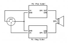
F6 in BTL/Bridge Style Configuration
Hi all,
My first plan was to build two F6 for bi-amping, I had already ordered 2 set of boards, power and signal transformers, jfets, and all others components, but reading some publications the idea to setup a bridged style configuration come to my mind, not looking for more power, just to keep the balanced signal from preamp.
I had in my stock or I had ordered components in quantity that permits good matching between all boards, so matching should not be an issue.
I’m a newbie with very limited knowledge of electronics, but had some experiences building other DIY projects like Aleph 2, F5 Turbo v3, UGS and Borbely balanced preamps, NJFET RIAA, etc., so I want to ask some questions to see if the attached picture configuration is possible
1) The Idea is to feed the input of each F6 stereo configuration with positive, negative and ground signal from a single balanced output from preamp as in the attached picture, also no single-ended input will be supported.
2) My speaker’s nominal impedance is 6 ohms, as far I understand the impedance load that sees each amplifier channel will be in this case the half of the impedance of each speaker, so in this case will be 3 ohms. Does F6 support this low impedance?, There are something or component in the F6 or power supply to specially take care in this case?
3) The power output of the F6 will be increased, decreased or keep as is, compared to a standard F6 configuration?
4) Mr. Pass in the document “Talks at Burning Amp Festival 2012” where he present the F6 amplifier, shows two possible power supply’s, one for mono and other slightly different for stereo configuration, in the case of this bridged style configuration which should I use?
Thanks,
Alejandro
PD. Thank you Mr. Pass for sharing your great designs with us 🙂
Attachments
There are no critical values in this or probably any of my DIY designs.
Just see to it that you use the same values for both channels. 😛
My day is made ! Thanks for everything that you gave us DIYers. Because of you I have been able to pursue very high level audio reproduction setup, without selling my house. Thanks once again.
Cheers.
My day is made ! Thanks for everything that you gave us DIYers. Because of you I have been able to pursue very high level audio reproduction setup, without selling my house. Thanks once again.
Cheers.
+1 on that.
Hi all,
My first plan was to build two F6 for bi-amping, I had already ordered 2 set of boards, power and signal transformers, jfets, and all others components, but reading some publications the idea to setup a bridged style configuration come to my mind, not looking for more power, just to keep the balanced signal from preamp.
I had in my stock or I had ordered components in quantity that permits good matching between all boards, so matching should not be an issue.
I’m a newbie with very limited knowledge of electronics, but had some experiences building other DIY projects like Aleph 2, F5 Turbo v3, UGS and Borbely balanced preamps, NJFET RIAA, etc., so I want to ask some questions to see if the attached picture configuration is possible
1) The Idea is to feed the input of each F6 stereo configuration with positive, negative and ground signal from a single balanced output from preamp as in the attached picture, also no single-ended input will be supported.
2) My speaker’s nominal impedance is 6 ohms, as far I understand the impedance load that sees each amplifier channel will be in this case the half of the impedance of each speaker, so in this case will be 3 ohms. Does F6 support this low impedance?, There are something or component in the F6 or power supply to specially take care in this case?
3) The power output of the F6 will be increased, decreased or keep as is, compared to a standard F6 configuration?
4) Mr. Pass in the document “Talks at Burning Amp Festival 2012” where he present the F6 amplifier, shows two possible power supply’s, one for mono and other slightly different for stereo configuration, in the case of this bridged style configuration which should I use?
....
1.OK
2.just make properly beefed PSU - say 350VA xformer per channel , appropriate (minimal) amount of capacitance is 8x15mF , per FW recipe
3.theoretically , bridge config will give you 4x power comparing to origin (half of bridge) ; practically , count on 3x ; so - you're already in who cares area
4.use one common PSU for both halves of bridge
F6 Just powered up with 1500VA Transformer
Just fired up the F6 running tests as we speak.
.jpg")
I built the F6 with the HA5002 buffer chip as the front end as I have plenty and is used in "The Albert". Since this is a high speed buffer chip it has excellent qualities for driving the F6 low output and high input impedance and a massive slew rate of 1500V/uS.
I'm running a slightly higher supply voltage of about 33V DC as the 1500VA 24VAC 24VAC transformer was available and have the buffer chip able to swing +20 -20V and as you can see I'm driving an 8 Ohm dummy load and getting about over 50 volts pp with just over an amp consumption. Yes the heatsink is getting toasty but the current has been stable for over an hour and the offset is steady at 1mV.
I will be conducting listening tests shortly.
Just fired up the F6 running tests as we speak.
I built the F6 with the HA5002 buffer chip as the front end as I have plenty and is used in "The Albert". Since this is a high speed buffer chip it has excellent qualities for driving the F6 low output and high input impedance and a massive slew rate of 1500V/uS.
I'm running a slightly higher supply voltage of about 33V DC as the 1500VA 24VAC 24VAC transformer was available and have the buffer chip able to swing +20 -20V and as you can see I'm driving an 8 Ohm dummy load and getting about over 50 volts pp with just over an amp consumption. Yes the heatsink is getting toasty but the current has been stable for over an hour and the offset is steady at 1mV.
I will be conducting listening tests shortly.
First Listening Tests
WOW!!!!!!!!!
I thought "The Albert" was good the F6 is spectacular!!!!!!!!
Mr Nelson Pass I cannot thank you enough. The sound is detailed, instruments are detailed, I can put my ear up to the tweeters and I cannot here any noise.
Outstanding so this is what a Class A amp sounds like?!

WOW!!!!!!!!!
I thought "The Albert" was good the F6 is spectacular!!!!!!!!
Mr Nelson Pass I cannot thank you enough. The sound is detailed, instruments are detailed, I can put my ear up to the tweeters and I cannot here any noise.
Outstanding so this is what a Class A amp sounds like?!
I agree, I am 66 years old and my taste in music now leans toward female jazz singers and blues mostly, Diana Krall etc, but I caught myself listening to Ariana Grande yesterday with all the boom, boom and enjoying it with the F6.
Thank you Zen Mod,
The transformers are 400va each, current capacitance is 8x22mF @63v.
Another question, I had the chance to change the power supply capacitors to 8x47mF @25v, but this seems to me very close to maximun rated voltage, the transformers secondaries are 2x18v, is Ok to use capacitors near it's maximun rated voltage?
Thanks,
Alejandro
I had the chance to change the power supply capacitors to 8x47mF @25v, but this seems to me very close to maximun rated voltage, the transformers secondaries are 2x18v, is Ok to use capacitors near it's maximun rated voltage?
They will work, but the useful lifetime will be reduced. Check the actual voltage on the caps
under normal operating conditions and see what it is. It will help to keep them as cool as possible.
Thank you Zen Mod,
The transformers are 400va each, current capacitance is 8x22mF @63v.
Another question, I had the chance to change the power supply capacitors to 8x47mF @25v, but this seems to me very close to maximun rated voltage, the transformers secondaries are 2x18v, is Ok to use capacitors near it's maximun rated voltage?
Thanks,
Alejandro
Pa is using Panasonic 15mF/25V in FW products
Thanks Rayma and Zen Mod,
My concerns are the same as Rayma about caps lifetime using it at near it's voltage limit, but Nelson in the FirstWatt products use 25v as Zen Mod says, maybe FW power supply caps are very long life class.
I will use the current power supply caps, they are from my Aleph-2 and have less than 3 years, latter will be replaced by a large ones.
Thanks,
Alejandro
My concerns are the same as Rayma about caps lifetime using it at near it's voltage limit,
Using a 105 degree C cap in this situation would also help to extend its life.
Last edited:
WOW!!!!!!!!!
I thought "The Albert" was good the F6 is spectacular!!!!!!!!
Mr Nelson Pass I cannot thank you enough. The sound is detailed, instruments are detailed, I can put my ear up to the tweeters and I cannot here any noise.
Outstanding so this is what a Class A amp sounds like?!
What are you using for a preamp?
Can you post a simple schematic showing how you have the buffer chip implemented?
I have several 5002s lying around, so I would like to try your combo sometime.
Thanks...
- Home
- Amplifiers
- Pass Labs
- The diyAudio Firstwatt F6