It’s gonna be very hard to top, for sure. I picked up a bunch of sits and vfets before prices went stupid but don’t think I’m quite ready for building with them yet and also not even sure which amp start with. Going to be an interesting comparison when it does happen.
🙂
🙂
Reading info re the M2X and saw this, "Capacitor “C0” is not present in the original M2 amplifier by Nelson Pass. The M2 owner’s manual explains that this makes it easier for tube preamps to drive an M2."
I imagine that this has to do with output/input impedance, would someone help enlighten me?
Thanks
PS If need be I will call out the

I imagine that this has to do with output/input impedance, would someone help enlighten me?
Thanks
PS If need be I will call out the

Sorry I can't help the above question.
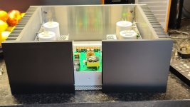
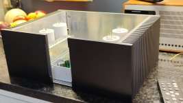
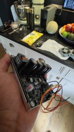
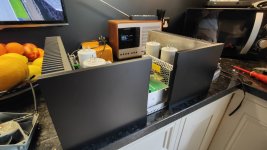
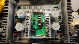
Here's progress on my hybrid M2X/3255 4 channel amp.
Features 4 separate SMPS. 2 X 24v serial for +/- rails for the M2X. Hopefully negating the M2 trafo noise pickup. And then (not pictured fully) 2 X 48v smps for the 2x 3e 3255 monoblocks.
Amp will be fed active XO signals so the class D will do the LF and the Class A the mids/tops. ,(passive xo got these ).
Quite a squeeze but should fit.
Attachments

I'd go with this passage from the manual as my reference. Emphasis added is mine.I imagine that this has to do with output/input impedance, would someone help enlighten me?
Thanks
"The input impedance is 100 Kohms, and the input capacitance is very low - only a few picofarads, so you will find it easy to drive it with single-ended tube equipment if you like."
With that said... As you well know... I don't know diddley. Bo wouldn't even answer my calls.
I am trying the IPS 6 on one channel and I have a DMM on the testpoints and I am stuck on 4 v,should it be 0v? what could be wrong?
IPS6's schematic is shown below.
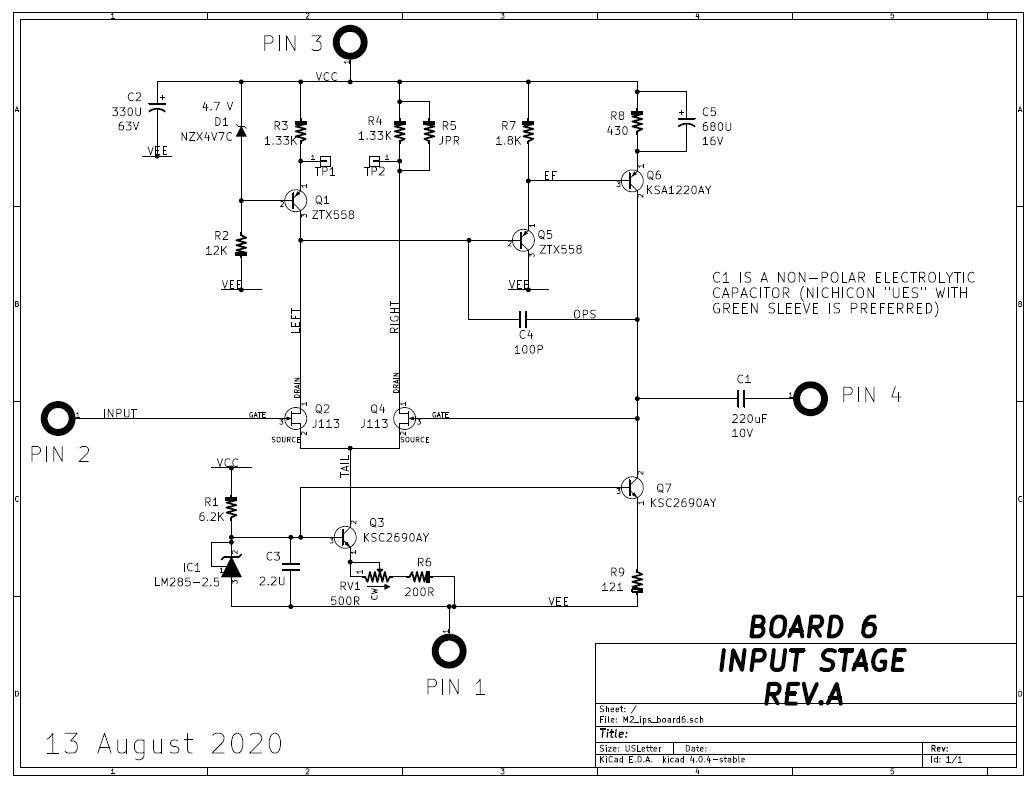
The test points are TP1 and TP2. Post #3408 of this thread describes the IPS6 adjustment procedure. I've copied it here to make it easily accessible to Members who may wish to offer opinions, advice, or learnings from the school of hard knocks:
The test points are TP1 and TP2. Post #3408 of this thread describes the IPS6 adjustment procedure. I've copied it here to make it easily accessible to Members who may wish to offer opinions, advice, or learnings from the school of hard knocks:
SETTING UP AND FINE-TUNING IPS6
After matching the two JFETs, stuff and solder the PCB. Do install resistors R3 and R4 but leave R5 unstuffed, unpopulated, and unsoldered.
Solder 3 cm long pieces of stiff, solid core hookup wire into the test point holes TP1 and TP2. AWG-22 works well. You will attach your voltmeter probes to these wires using crocodile clips.
Apply power supplies to the IPS6 board and connect your voltmeter to TP1 and TP2. It doesn't matter whether you connect TP1 to Meter+ or Meter-.
Twirl the knob of RV1 whichever direction makes the voltmeter reading smaller. Your goal is to find a setting which makes the meter read zero. When you get close, step away from the amplifier for 10 minutes and let it warm up a little.
Again twirl the knob of RV1 on the IP6 card, to make the voltage between TP1 and TP2 as near to zero as you can get it.
Step away for another 20 minutes.
Now twirl the knob of RV1 until the voltage between TP1 and TP2 is zero. It will still creep around, slooooowly, and that's okay. Just find a setting which makes the meter read zero, all these many minutes after power-on, and then ignore subsequent meter creep. Disconnect the crocodile clips, put a dot of some kind of sealing paint on the RV1 knob (Loctite, nail polish, etc), done. When you power off the M2, cut away and discard the two hookup wires attached to test points TP1 and TP2. You don't need them any more.
OPTIONAL: if you wish you can solder in a piece of wire (a "jumper") for R5. I never did, for all of the boards I built and tested and adjusted and sent out to third party listeners / reviewers. But you can do so if you wish. It's your choice; it's your option.
Last edited:
Capacitor C0 is an optional RF filter on the input of M2x, which you can choose to include if you have issues with RF ingress in your system.
However, to most tube preamps, an additional 220pF of input capacitance is very difficult to drive and would be like a swift kick to the tender sphericals, and said preamp will be rolling around on the floor moaning in pain, gasping for air, illustrating again why C0 is made optional.
However, to most tube preamps, an additional 220pF of input capacitance is very difficult to drive and would be like a swift kick to the tender sphericals, and said preamp will be rolling around on the floor moaning in pain, gasping for air, illustrating again why C0 is made optional.
What do you mean? Install it if you have RF problems (I.E., you're getting cheap SMPS noise or broadcast radio signals into your system) and don’t use it if you are using an unbuffered tube preamp.
It’s up to you to decide if it will be useful.
It’s up to you to decide if it will be useful.
One of my preamps is a 6N7S based unit so when you said "like a swift kick to the tender sphericals" it makes me think I should not include C0. Just curious as to how it would effect the sound.
There is a well-known and universally applicable response to the question:
"What would happen if I did X?"
"What would happen if I did X?"
Yes, try it, I know, but certainly others have and can answer a simple question. Experimenting is 1 way to gain insights but it is also helpful to have knowledge as to what is happening.
"What would happen if I did X?"
when I was a Kido .........full blast down the slope/road of bridge, on my bicycle
- what will happen if I suddenly rotate my handlebars fully right?

@Toys4Boys You are missing the point entirely. The most important question you need to answer is, “Do I need to include C0?”
Reasons why you might choose to use C0 are answered in the documentation as well as in this discussion now. Reasons to not use it are also in the documentation and in this discussion.
C0 is optional and using it or not won’t have any effect the normal operation of M2x.
Reasons why you might choose to use C0 are answered in the documentation as well as in this discussion now. Reasons to not use it are also in the documentation and in this discussion.
C0 is optional and using it or not won’t have any effect the normal operation of M2x.
It's probably either (a) poor soldering; (b) transistor installed backwards; (c) resistors swapped; or (d) failed component.I am trying the IPS 6 on one channel and I have a DMM on the testpoints and I am stuck on 4 v,should it be 0v? what could be wrong?
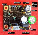
When you study the IPS6 circuit schematic in post #6,766, you will see that there is no ground connection on the IPS6 daughter card. None! So you will need to measure DC voltages with respect to some other reference node instead of ground. I recommend you use node "VEE" on daughter card (bolt #1) as your measurement reference node. Connect the negative lead (black) of your DVM to bolt #1 and leave it there. Remember, this is not GROUND, there is no ground. Your meter is connected to VEE.
Then on the failing IPS6 card, measure the following DC voltages:
- BOLT3 ("VCC") to BOLT1 ("VEE")
- node OPS to BOLT1
- R1 flywire to BOLT1
- R9 flywire to BOLT1
- R7 flywire to BOLT1
- R8 flywire to BOLT1
_
Attachments
And here are the results.I am using a bench power supply set to 50v.
- node OPS to BOLT1 = 8,5v
- R1 flywire to BOLT1 = 2,06v
- R9 flywire to BOLT1 = 1,44v
- R7 flywire to BOLT1 = 46,81v
- R8 flywire to BOLT1 =47,37v
R1 flywire to BOLT1 = 2,06v
That's a problem. There may be several other problems too, who knows, but this is definitely a problem.
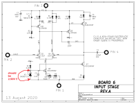
Resistor R1 and 3-pin voltage reference IC1 work together, to set the voltage on the flywire of R1. That flywire is supposed to be exactly 2.50 volts above BOLT1 because IC1 is a precision device. 2.06 volts is badly wrong.
Carefully inspect your not-working IPS6 and compare it against what you see on the yes-working IPS6. Does R1 have the same colored bands on both boards? Is IC1 facing the same direction on both boards? Somehow, your not-working IPS6 board is getting the wrong answer from these two components. If you are curious you can put the yes-working IPS6 board on your test fixture and measure its voltage from R1 flywire to Bolt1. See if it reads "2.06 volts" like the bad board. (answer: no it doesn't)
_
Attachments
- Home
- Amplifiers
- Pass Labs
- The diyAudio First Watt M2x