I reckon yet another thing to learn from that story is - if you see some misterious things happening and start suspecting issues like bad batch of PCBs from diyStore, mislabled resistors from Mouser or something even more gruesome, - pause, make 3 steps back and look into the mirror - "*we* are the gremlins", as ZM once said...
ZM can be a bit facetious at times.

I am a software developer, and we have a very frequent saying: “I found the problem!, it was between the chair and keyboard!” 🙂I reckon yet another thing to learn from that story is - if you see some misterious things happening and start suspecting issues like bad batch of PCBs from diyStore, mislabled resistors from Mouser or something even more gruesome, - pause, make 3 steps back and look into the mirror - "*we* are the gremlins", as ZM once said...
Yeah, it’s usually man-made errors rather than crazy scenarios where a weird printed PCB met a mislabeled part that had an internal malfunction. Human error is much more likely, always. That doesn’t mean the other things don’t happen, but they happen less often.
Rafa - we used to use roughly the same phrase...
In the more extreme situations, we called it a code "Eye Dee Ten Tee" (phonetically)
In the more extreme situations, we called it a code "Eye Dee Ten Tee" (phonetically)
Yes this is great advise. Some of us have been screwing things up for so long that the process of eliminating all the errors I could have made before suspecting any thing else is deeply ingrained in my trouble shooting flow chart. If it has more than two parts it is possible for me to get one wrong. I just embrace it and smile.
I am a software developer, and we have a very frequent saying: “I found the problem!, it was between the chair and keyboard!” 🙂……
In my line of work it used to be ‘Was a severe headspace problem’.
question about sparkfun adapter
Does the sparkfun adapter turn the smd 180º from the way it would solder directly to the board? The one on the right in the photo has the square pads lined up. I finally got around to putting these adapters together with the opa1611 and this is confusing me. I've tried Austin, Cedarberg, and Tucson with the opa604 and lt1122, now I want to try the opa1611. I wish we could buy these daughter cards in individual pairs, somehow I lost one Norwood board. I'm currently enjoying my F6 (led bias mod and IRFP150) now that it's cooling off here in Austin.
Does the sparkfun adapter turn the smd 180º from the way it would solder directly to the board? The one on the right in the photo has the square pads lined up. I finally got around to putting these adapters together with the opa1611 and this is confusing me. I've tried Austin, Cedarberg, and Tucson with the opa604 and lt1122, now I want to try the opa1611. I wish we could buy these daughter cards in individual pairs, somehow I lost one Norwood board. I'm currently enjoying my F6 (led bias mod and IRFP150) now that it's cooling off here in Austin.
Attachments
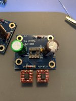
Yes - dot on SMD Op amp does not align with square “pin 1” on the DIP. I don’t think it’s 180-degrees more like 90-degree.
Double check with DMM, one probe on pin 1 on SMD and other probe on square pin on adapter, if you get a beep (continuity) you are good.
Double check with DMM, one probe on pin 1 on SMD and other probe on square pin on adapter, if you get a beep (continuity) you are good.
I must say this again,how I change the IPS back and foward I comes to the conclusion that Black Forrest has the best overall performance.
Detalied,soundstage and bass perormnce....
Thanks for doing this..... 🙂
Detalied,soundstage and bass perormnce....
Thanks for doing this..... 🙂
I have a question about the Ishikawa card.
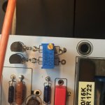
I tried to bypass C1 but had a few mV offsets.
This can be reduced on the M2 Tea-Bag's PCB by installing a 20R pot as shown in the picture.
Can the same be done on the Ishikawa card by installing RV1 = 20R instead of R1 and R2? Then set 0r on the Edcor input?
I tried to bypass C1 but had a few mV offsets.
This can be reduced on the M2 Tea-Bag's PCB by installing a 20R pot as shown in the picture.
Can the same be done on the Ishikawa card by installing RV1 = 20R instead of R1 and R2? Then set 0r on the Edcor input?
Attachments
I have a set of M2X boards [A & B]. Not sure how I ended up with one more set than I needed to build my amp. Though it is often helpful to have a bare board to refer to once you are deep in the weeds.
I'd like to pass these on for those starting this great build adventure, which is guaranteed never to end with all the new cards.
If interested, send me a message. I just ask for $7.00 to cover shipping, payable to my PayPal account.
I'd like to pass these on for those starting this great build adventure, which is guaranteed never to end with all the new cards.
If interested, send me a message. I just ask for $7.00 to cover shipping, payable to my PayPal account.
Hello Folks, does anyone know how to modify a bit smaller of M2X's biasing voltage fot the output stage FET, because of I completed it in a cabinet with smaller heatsink, so the heat emission not so quick enough.
The question is still open 🙂

I had the Mountain View card for half a year. Yesterday I launched M2x with Tucson. The first thing I had to do was set the offset. It was 120mV. It floats definitely more, but I managed to set it to +/- 5mV. The opamp is LT 1122. I am a bit worried about the high temperature of the opamp because it burns my fingers quite quickly. The listening comparison is not ready yet.I have a question about the Ishikawa card.
I tried to bypass C1 but had a few mV offsets.
This can be reduced on the M2 Tea-Bag's PCB by installing a 20R pot as shown in the picture.
Can the same be done on the Ishikawa card by installing RV1 = 20R instead of R1 and R2? Then set 0r on the Edcor input?
Hello All,
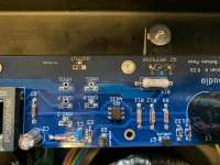
I just finally got around to finishing up on my MX2 build. But I have an issue with one of the channels.
I have about .744v dc present at pin4 and R5 on channel A and this is not present on the other working channel. I am a bit lost where to go from here to locate the issue. This is also present with the daughter card(s) removed.
so far:
R13, R14 - 0.630v
offset - 0.0v
PS - 22.5v +/- on both rails
Sound does come out of this "bad" channel but its not good or even close to the other channel in volume or quality.
Thanks in advance to anyone that can help point me in the right direction.
Please post a series of well-lit, in-focus photos.
Have you tried the operative channel daughter card on the misbehaving channel? (And vice-versa)
What daughtercard are you using?
Have you tried the operative channel daughter card on the misbehaving channel? (And vice-versa)
What daughtercard are you using?
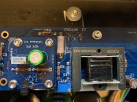
Yes I did swap the cards between channels and they work on the good channel B and the same issue is present on channel A.
Ishikawa - W/ Toshiba jfets from the diyaudio store
and thank you for the quick reply.
Quick note: I am using a T style heatsink and the connectors have been moved to the underside of the board
Ishikawa - W/ Toshiba jfets from the diyaudio store
and thank you for the quick reply.
Quick note: I am using a T style heatsink and the connectors have been moved to the underside of the board
Attachments
Last edited:
Ishikawa board C1 question
i´m just in process of ordering parts for M2x Ishikawa Iteration.
When i crosschecked the mouser parts (actually im ordering from reichelt in Germany) i came across a probelm.
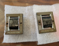
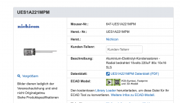
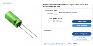
C1 (Ishikawa board) is specified by Mark as "nonpolar", preferred is Nichicon green sleeve (Muse?) but all the C's i find are polar ones : (
The symbol for C1 in schematic shows two equal thick lines, indicating nonpolar.
And yes, of course, it shows that my knowledge is too poor to understand what C is asked for electrically in this situation 😀
So the attached ones seem to be wrong, right?
tnx very much,
stefan
i´m just in process of ordering parts for M2x Ishikawa Iteration.
When i crosschecked the mouser parts (actually im ordering from reichelt in Germany) i came across a probelm.
C1 (Ishikawa board) is specified by Mark as "nonpolar", preferred is Nichicon green sleeve (Muse?) but all the C's i find are polar ones : (
The symbol for C1 in schematic shows two equal thick lines, indicating nonpolar.
And yes, of course, it shows that my knowledge is too poor to understand what C is asked for electrically in this situation 😀
So the attached ones seem to be wrong, right?
tnx very much,
stefan
Attachments
Last edited:
- Home
- Amplifiers
- Pass Labs
- The diyAudio First Watt M2x