Hello bullittstang,
the phenomena with the M2X on the dimbulbtester is well known. Dimbulbtester goes off and lights up again after a few sconds.
This was mentioned and discussed a few times in this very long thread.
My M2X does exactly the same. I would test it without any speaker (and without the dimbulbtester!) and adjust the offset.
If you can't adjust your offset at speakeroutput below 50mV (better below 10mV) you should read the info about the 'blasphemous heresy' -change = change of resistor R6 and trimpot.RV1:
post#3 (in this thread) from Mark Johnson:
3. WARNING: BLASPHEMOUS HERESY! DO NOT READ THIS! Some DIY builders of the M2 amplifier, using the very fine “Tea‐Bag” circuit board, have reported a problem to the diyAudio forums. Their M2 amplifier’s output offset voltage is negative, and no setting of trimmer resistor RV1 removes this negative offset. I would like to gently mention a possible fix: leave R7=47K, but change R6 to 37K and change RV1 to 20K. Now (R6+RV1) can vary from 37K to 57K, in other words, from (10K less than R7) to (10K more than R7). This lets you null out either polarity of offset voltage. However, to faithfully reproduce Nelson Pass’s original M2 design, the M2X schematic and PCB silkscreen do not include this modification. M2X has R6=47K and RV1=5K. If you decide to make this R6,RV1 modification on your M2X, don’t tell anyone. And don’t quote me.
Cheers
Dirk 😀
Dirk,
I did this r6 rv1 variant for no other reason that I happened to have the 20k trimmer handy when I was building the amp. I got lucky I guess. 😉
Update - powered up fine, set offset to 0 on both channels without any problems.
I let it idle for 40-45 mins and heatsinks topped out at 95F (5U case with full length heatsinks), so everything is working well.
Should get RCAs and shielded cable tomorrow and hope to have it finished over the weekend.
I let it idle for 40-45 mins and heatsinks topped out at 95F (5U case with full length heatsinks), so everything is working well.
Should get RCAs and shielded cable tomorrow and hope to have it finished over the weekend.
Hello bullittstang,
first: congratulations and enjoy your M2X ! 🙂
Also, it is good to have the data point of a successful build right now. Did you buy your boards from the store recently, or a long time ago ?
Best regards, Claas
first: congratulations and enjoy your M2X ! 🙂
Also, it is good to have the data point of a successful build right now. Did you buy your boards from the store recently, or a long time ago ?
Best regards, Claas
to bullittstang
Good morning bullittstang,
good to hear, that your M2X is up and running! 😉
Now you will go on a long 'listening-journey' with different input-buffer-boards.
Have fun! Enjoy a fantastic amp!
Cheers
Dirk
Good morning bullittstang,
good to hear, that your M2X is up and running! 😉
Now you will go on a long 'listening-journey' with different input-buffer-boards.
Have fun! Enjoy a fantastic amp!
Cheers
Dirk
Whats the purpose of this one?
If you are asking the purpose of a DBT... In general, when used properly, it is to allow only a reduced amount of current through the device under test. Generally, we use them when troubleshooting or during initial startup either with or without a variable transformer.
Why? So, we potentially do not release the magic smoke if we accidentally do some of the following things (which a DBT has "saved" me from). There are certainly many more. Maybe we should start a thread... 😀 😀
- Short a rail of your PSU to GND b/c you were a dolt and used too large a star washer, and it cut through an adjacent trace.
- REALLY ook up and send all available current through the output devices b/c you forgot to adjust the bias pot properly before initial startup.
- Had an output device shorted to the heatsink.
Hello bullittstang,
first: congratulations and enjoy your M2X ! 🙂
Also, it is good to have the data point of a successful build right now. Did you buy your boards from the store recently, or a long time ago ?
Best regards, Claas
I bought the boards in March 2021 from DIY store. PSU is a Pass clone from eBay, but very well built.
All parts were from Mouser or Digi-Key (bought in April) using the BOMs, with only a couple substitutes.
Hello bullittstang,
first: congratulations and enjoy your M2X ! 🙂
Also, it is good to have the data point of a successful build right now. Did you buy your boards from the store recently, or a long time ago ?
Best regards, Claas
Why raise this question when there is absolutely nothing wrong with store PCB boards, new or old?
We had a discussion ongoing in the past several weeks where one builder has a problem with his build, and he couldn't rule out a board issue contributing to the problem.
So it is good to see that the boards that were sold in March don't show any problems.
Best regards, Claas
So it is good to see that the boards that were sold in March don't show any problems.
Best regards, Claas
I wouldn't expect a board problem given that there are so many builds, but don't have the boards in hand to verify myself.
As promised, here is the report on the replacement M2X boards. Four were sent and all four are defective. This is the specific reason. When only two resistors, R12 and R11 are added to an otherwise blank card, the reading from the bottom of each reads 221 ohms, not the correct 321. So the board is creating some additional, faulty path from R12 to R11 that negates the 100 ohm value of R12 and supplies only 221 ohms. The schematic makes it clear that no such path should exist and that the path from R12 to R11 is direct with no other components installed.
This value, along with the incorrect path, will keep the Optocoupler from limiting the voltage rise and, therefore, none of these boards will operate.
To be careful, one of the boards had the 3-step build mentioned earlier completed. First R14, R12, and R11 were installed. Incorrect reading of 221 at the bottom of the resistors and from R14 to Pin 2, 4N35 Opto. Then the rest of the resistors for this portion of the circuit were added: R9, R13, R10, and R8. Same 221 ohm reading. Finally, the Diodes, transistors, and OptoCoupler were installed, the latter with a Dip-6 socket to ensure security. Same 221 ohm reading and the same defective board that will not, of course, operate.
The post is supplied for potential purchasers of these boards so that they know that one person, who has built 4 of these boards completely, and has tested four others, has received only one working board. Because of these incorrect boards, over $400 has been spent on wasted parts and over $1K on the total project including power supplies and chassis that now serve no purpose.
The DIY store has been informed, now 3 times, of this problem and should test their remaining boards for the problem described above before continuing to send out defective merchandise. Failure to do so will generate many disgruntled DIYers who have no working M2X and lost monies.
Not sure if this would just further muddy the waters but I just happened to have some partially assembled M2x boards. I can offer some pics if anyone would think it would be helpful.
Regards,
Dan 🙂
Regards,
Dan 🙂
dantwomey: then please check the value at the base of R12 to base of R11 and see if it is 221 or 321. Also let us know whether your boards are recent purchases or from an earlier buy.
As promised, here is the report on the replacement M2X boards. Four were sent and all four are defective. This is the specific reason. When only two resistors, R12 and R11 are added to an otherwise blank card, the reading from the bottom of each reads 221 ohms, not the correct 321. So the board is creating some additional, faulty path from R12 to R11 that negates the 100 ohm value of R12 and supplies only 221 ohms. The schematic makes it clear that no such path should exist and that the path from R12 to R11 is direct with no other components installed.
Craigl59, If you measure 221 ohms with just 2 resistors installed, then it's most likely there should be some path on the board shorting the two ends of R12. Measure just R12 first (you should get a short there) and then put one probe on the bottom point of R12 and poke arround with the other probe to find the path that is shorting the R12.
Somehow, it's quite difficult to believe for me that the diyAudio boards are deffective. That should be a very very rare chance indeed.
All the best.
Alvis
Alvis: Please re-read my explanation above: no components other than the 2 resistors are checked at first. So any short, if existing, must be a board problem. Have spent the time to check the correct continuity of each component on the board and to also check for shorts to other components -- for all of the board parts and for all the short possibilities. Found none and this is, of course, curious. But the fault described above exists, is on 7 of the 8 boards sent to me, and will not go away. Nor has it ever been explained by others on this board. The proof that this is a board issue comes from the fact that one board sent to me operates correctly, has the correct reading of 321 from R12 to R11 base, and functions properly within the circuit.
Dantwomey can help us a bunch by measuring R12 and R11 on his boards and reporting his readings -- along with the date of his purchase.
This is not about belief, this is about the described facts. No-one wants working boards more than me.
Dantwomey can help us a bunch by measuring R12 and R11 on his boards and reporting his readings -- along with the date of his purchase.
This is not about belief, this is about the described facts. No-one wants working boards more than me.
Last edited:
So the board is creating some additional, faulty path from R12 to R11 that negates the 100 ohm value of R12 and supplies only 221 ohms.
Another way to say that is: the PCB is short-circuiting R12.
If that is the case, then a DMM will read zero ohms across R12 when it is installed, and from pad to pad if no R12 is installed.
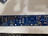
Here are pics of the 2 testings -- they just show what is described and do not, as far as I can tell, provide any helpful data. All of the connections are properly made and because of the board problem, are irrelevant to the issue.
Attachments
Alvis: Please re-read my explanation above: no components other than the 2 resistors are checked at first. So any short, if existing, must be a board problem. Have spent the time to check the correct continuity of each component on the board and to also check for shorts to other components -- for all of the board parts and for all the short possibilities. Found none and this is, of course, curious. But the fault described above exists, is on 7 of the 8 boards sent to me, and will not go away. Nor has it ever been explained by others on this board. The proof that this is a board issue comes from the fact that one board sent to me operates correctly, has the correct reading of 321 from R12 to R11 base, and functions properly within the circuit.
Dantwomey can help us a bunch by measuring R12 and R11 on his boards and reporting his readings -- along with the date of his purchase.
This is not about belief, this is about the described facts. No-one wants working boards more than me.
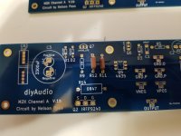
Here is a picture of my partially completed boards, bought in March 2021. Check the revision date with yours because I just completed these last night, started up fine and played music without an issue.
Looks to be a DMM issue, resistor issue or a measurement issue at this point, because it’s not the DIYA boards.
Edit: noticed Q6 on bottom board is backwards, obviously that was fixed before powering it up.

Tim writes:
"If that is the case, then a DMM will read zero ohms across R12 when it is installed, and from pad to pad if no R12 is installed."
R12 reads the correct 100 ohms across and OL from pad to pad when R12 is removed. Again, as noted above, cannot tell why the problem is ocurring and that all of the continuity and short tests made show no problems. But the incorrect reading of 221 for R14 to 4N35 will not go away, is on all of the non-working boards, and IS NOT on the one board that I have that is working.
YOU TELL ME why this value can appear with only two resistors installed -- please do so.
- Home
- Amplifiers
- Pass Labs
- The diyAudio First Watt M2x