There are two different nomenclatures in use up to now. The schematic shows anode of LM385 at Pin3, cathode at Pin2. The data sheet from National Semi I attached in #5504 shows anode at Pin1, cathode at Pin2.
But the cathode is always at Pin2, and Pin2 is always the middle pin. Please don't introduce another nomenclature, that would be confusing.
The way I trace the boards from the photos:
Middle Pin (2) is cathode.
Right Pin (1 or 3, doesn't matter) is anode.
You need to measure from the middle pin and from the right pin
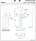
P.S.: On the data sheet from National Semi attached to #5504, you need to look at the TO-92 package, because that's what you have, not the SOT23.
On my 385s and on the schematic, the middle pin is #1 and the right pin while facing is #2. #3 is the left side and it is always dead. So the order as shown on the schematic is 3-1-2. This is what gives me results while testing.
What is a resistor string measurement?
Wait WHAT?! Please link your exact part number that you bought. You may have previously, but I think you've found your issue.
IAIMH: Thanks for all the help. You state:
"Pin 1 is Anode, Pin 2 is Cathode. IMPORTANT TO LET US KNOW IF THAT IS NOT THE CASE."
So this is, I think how I am measuring the 385s -- as facing = 3-1-2. So #1 (middle) is anode and #2 (right) is cathode. Correct?
And all of the paths have been checked for continuity and are correct.
You state:
"So, how could both your working and non-working boards be the same, and both have a different than expected resistance measurement?"
They are not the same -- the one difference is in the R14 to Pin 2 Q5 reading of 332 ohms on the working and 221 on the non-working. Am at a loss as to how this can be with the other differences detailed in the R14 to Pins 1-2 of Q7 that are clearly reversed.
@grataku: I have compared Cedarburg and Vfet (I had 6L6's here for taking pics).... Both exceptional—I didn't do a super critical examination but we had it on for a couple of weeks and everyone here loved it—going back to M2X/Cedarburg definitely wasn't super massively different (they are different though)—but my M2X are mono blocks and I think that does something in our space to our ears, soundstage blah blah...musicality was 100% there in both amps... I'm building Vfet now.... as monos... Vfet was absolutely silent in our speaks—M2X has the faintest something when the ear is right on the tweeter. IDK... I find that evals of this stuff, I don't really know how I feel until I spend time with the new thing (a week plus)—and then go back to the "old" thing... then I feel I know "something"... not questioning what you are saying at all... maybe go over the boards with a fine tooth comb? Ha. Another thought: Speaker synergy? You have some insanely awesome speakers, I have never heard them however. These are mine: OSMC
Crosspost with Mark! He knows!!!! Another reason to celebrate all our differences...I do think the whole system and all components and the room are a balancing act... I wish we could all travel around and listen to all the amazing systems that people here have created. That would be insanely educational and fun.
Guys, I am having a bit of fun here but I kind of believe in absolutes, too. 😀 Again, I VERY much appreciate the choices that MJ and others have brought to the table. I am simply reporting my findings that hopefully may help others with preferences similar to mine. I think it's more useful than burying them and forget all about it.
Having said that the cedarburg is no good 4me, except for the bass which is vastly superior to the sloppy V-fet bass that I love to hate. 😉 😉 Not only the overall musicality is not there but the mid-high sound straight up broken.
So much so that it made me question the correctness of the built. Then again, I had very bad results with OPAs opamps which I find very dark and dull.
IAIMH: Am ordering and receiving the same BoM part number as 595-LM385LPR-1-2. Have discussed this multiple times above and checked the device name with the documentation. The part number is 385-12 then T1. Device name says it should be 385B12 but have been assured above that it is the correct part.
You tell me.
You tell me.
I'll let you catch up. So many of us want you to be successful in your fix that we're probably overwhelming you with help.
Don't worry about how you're measuring them. Send us the link to the actual part you bought. We can tell you what the pins should be and how it should be oriented. As long as the middle pin is the cathode (pin 2) and one of the other pins is the Anode, you're good to go. However, the right-most pin on the board must have the anode. The left most pin is a trace to nowhere. 😀
I was only referring to the boards being the same in that one tiny section of measurement. - not the rest. My apologies for the confusion. Thanks for letting me know that did not make sense.
Edited to add the data sheet for the part listed. No... I did not read back too far. I don't intend to. If it's too much trouble to repost a part number or a measurement, there's no need to get frustrated, I'll just bow out.

For this part, it should be oriented per the silkscreen.
Don't worry about how you're measuring them. Send us the link to the actual part you bought. We can tell you what the pins should be and how it should be oriented. As long as the middle pin is the cathode (pin 2) and one of the other pins is the Anode, you're good to go. However, the right-most pin on the board must have the anode. The left most pin is a trace to nowhere. 😀
I was only referring to the boards being the same in that one tiny section of measurement. - not the rest. My apologies for the confusion. Thanks for letting me know that did not make sense.
Edited to add the data sheet for the part listed. No... I did not read back too far. I don't intend to. If it's too much trouble to repost a part number or a measurement, there's no need to get frustrated, I'll just bow out.
For this part, it should be oriented per the silkscreen.
Last edited:
chede: yes, have been measuring from the middle and right pins only. But then am assuming from your helpful explanation that the Pin designated as Pin 1, Q7 in IAIMH's summary is the right pin and pin 2 is the middle pin. Is this correct? If so, then I have been measuring them the other way around.
Last edited:
IAIMH: Please do not bow out -- your help is very great. Here's the link:
https://www.mouser.com/ProductDetai...cg1Lp/toDxnHtW7Gv/73lva6HKDMmHULtDWXIy1KwBA==
Thanks for your expertise.
https://www.mouser.com/ProductDetai...cg1Lp/toDxnHtW7Gv/73lva6HKDMmHULtDWXIy1KwBA==
Thanks for your expertise.
OK, Pin 1 is the right side and Pin 2 is the middle as described by IAIMH. Now redid all of the measurements and agree completely with IAIMH's summary above. The only difference is R14 to Pin 2 Q5 that is 322 ohms on the working board and 221 non-working. This is the descrepency that has been plaguing me for the last several days and for which we have not found an answer.
chede will do that today. Then I check the resistor values? Again, the continuity checks done yesterday show all the boards in complete agreement with the schematic.
chede: just removed Q5, Q6, and Q7 on the new, channel B card that has been checked completely with the schematic for continuity. The disappointing news is that the R14 to pin 2 (now open) slot for 4N35 is the same, incorrect 220 ohms.
Now this board has been exhaustively checked for correct part build and schematic agreement. The only reason I can think of for this problem is that there is a board issue. Do you agree?
Now this board has been exhaustively checked for correct part build and schematic agreement. The only reason I can think of for this problem is that there is a board issue. Do you agree?
chede: just removed Q5, Q6, and Q7 on the new, channel B card that has been checked completely with the schematic for continuity. The disappointing news is that the R14 to pin 2 (now open) slot for 4N35 is the same, incorrect 220 ohms.
Now this board has been exhaustively checked for correct part build and schematic agreement. The only reason I can think of for this problem is that there is a board issue. Do you agree?
It's odd... definitely. Even though on the schematic things are nice and tight... tracing the path through the boards can be very valuable. I'd assume that's where Chede is heading. So, how can current get from R14 to Pin 2 of Q5 with Q5, Q6, and Q7 removed?
Below is not proper, but easiest to describe. Observations are on left board with silkscreen oriented right side up. I can't seem to get a good enough photo to post and edit to show the traces. If you take a look at your boards... it's easy to follow the trace from R14(left) to R12(bottom) through R12 up to pin 1 of R7 and over to R11(Top). On the underside of the board. R11(bottom) connects to pin 2 of Q5.
Check resistance with one probe at the bottom of R11 and the other at the bottom of R12. If it's not 321R - we know where to start looking again. If it's 321R, we'll move along.
You can check if the pads for Pins 1 and 2 of R7 are shorted, but it's unlikely since you measured 100R earlier (showing R12+R14).
Edited to add for clarity - after assuming incorrectly that you removed the parts from a previously bad board.... I may have things mixed. We have been dealing with a channel A (traditionally left channel) board. Why are we removing parts and measuring a different board? The traces I described above are for a Channel A board even though it's very similar for B.
Last edited:
@ItsAllInMyHead
You certainly mean Q7 instead of R7....
If you take a look at your boards... it's easy to follow the trace from R14(left) to R12(bottom) through R12 up to pin 1 of R7 and over to R11(Top). On the underside of the board. R11(bottom) connects to pin 2 of Q5.
...
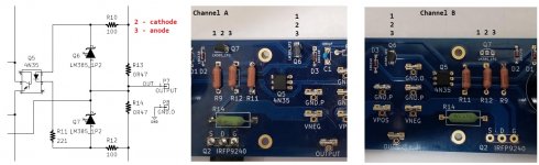
IAIMH: The check on R11 and R12 has been reported on by me several times above. It is 221, not 321 on all 4 boards I have. Since all of the non-working boards (3) are built exactly the same and have the same problem, I chose to remove the Q series from the new, unused Channel B board to ensure that no prior electronic issue would impact on the accuracy of the results. Have determined that if the board reads 221R from R14 to Pin 2, 4N35, it is unusable anyway.
DIY is sending some replacement boards and I will test them anew this way:
Will add R11, R12, and R14. Then will check R from R14 to pin 2 socket of 4N35. According to the schematic, this is a discrete path only affected by Q7 and we have established above that Q7 does not affect the R.
Would suggest that others with cards who have not yet built should also check this path -- otherwise you risk my dilemna of several hunderds of dollars spent on useless parts and cards. If there is some way that other parts can affect the above test reading, then please tell me now. But the schematic is clear and discrete.
And another problem that I reported on above is that the working board reads 322 R from R14 to Pin 2, 4N35 as it should. But, if you do the test suggested my IAIMH and reported on by me above, R12 to R11 reads 221 on this working card. So, where this working board gets the additional 100 R for Pin 2, 4N35, is another mystery.
Thanks all. This forum is superb in helping others with their issues and, as always, I recognize your effort.
Last edited:
IAIMH(2): Thanks for the trace information and have been looking at this myself to see if there are alternate paths for the area. In addition to your description (with the Q7 correction) it seems that at least one other part either connects or runs under R9, R11, and R12. D3 to R9 and Q7 is specified in the schematic.
Again, am trying to determine if there can be any other R influence on the path from R14 to R12, to R11, then to 4N35, Pin 2. If anyone has info here, thanks for your response.
Again, am trying to determine if there can be any other R influence on the path from R14 to R12, to R11, then to 4N35, Pin 2. If anyone has info here, thanks for your response.
- Home
- Amplifiers
- Pass Labs
- The diyAudio First Watt M2x