M2X TUCSON Daughter Board: Notes for Builders
Good Answer Chiptech
Paragraph 3 of Builders notes.
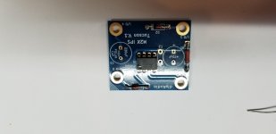
3. Pin 1 indicator. The thru hole footprint for the opamp has a square pad where
pin 1 goes. It also has the numeral “1” on the front silkscreen, next to pin 1.
The SMD footprint is rotated 90 degrees counterclockwise (so the pads won’t
collide!) Its pin 1 is marked with front silkscreen text, and with an arrow.
Good Answer Chiptech
Paragraph 3 of Builders notes.
3. Pin 1 indicator. The thru hole footprint for the opamp has a square pad where
pin 1 goes. It also has the numeral “1” on the front silkscreen, next to pin 1.
The SMD footprint is rotated 90 degrees counterclockwise (so the pads won’t
collide!) Its pin 1 is marked with front silkscreen text, and with an arrow.
Great quotation, @A321Drvr . The M2x Tucson PCB contains a few mileposts and markers to assist the builder in searching for pin #1 . Image below.
And of course there's always YouTube
Finding pin 1 on an IC chip - YouTube
_
And of course there's always YouTube
Finding pin 1 on an IC chip - YouTube
_
Attachments

This is a good reminder to check the individual daughter board notes before assembling. In other words, do as I say, not as I do.
What we are saying is.... read and research. The same thing our Airbus pilot did when he quoted the build guide.
People here are very helpful, but they like to see us noobs, at least try and get the answer on our own. Take the time to read and find the answers, search this forum and the net too.
I'm taking on the Honey Badger build right now... I've been reading the build thread for days now... I'm on page 142 of some 430 pages. I also have the build guide and schematic in front of me while doing so. I have a WORD doc open to drop notes in as I read through the threads and build guide. In the WORD doc I link with posts, pages, pics, notes anything that I might need when I actually start the build. I haven't even ordered the parts yet, because I need to take into account my system and what I want to achieve with this build.
Anyway, one new guy to another, people are more willing to help if they know you have done your best to find the answers on your own. Some do it with tack by asking you a question in return which gives you a hint as to a course of action, or find the answer on your own. Others, just read the question knowing we didn't try and move on without response.
A lot of this stuff is over my head, and frankly always will be, but it's not going to be for lack of effort on my part.
JT
Last edited:
willing to build low power M2x I would like to lower the PSU voltage.
what would be the minimum to keep an acceptable mosfet capacitance?
is 10V+10V too low?
I need max 2W on 8ohm for mids and tweeter,
maybe skipping the buffer card and edcor, driving directly the gates from the preamp/active crossover
what would be the minimum to keep an acceptable mosfet capacitance?
is 10V+10V too low?
I need max 2W on 8ohm for mids and tweeter,
maybe skipping the buffer card and edcor, driving directly the gates from the preamp/active crossover
Yes, I think 10 + 10V is too low.
The lowest I will be sort of comfortable with is maybe 15 + 15.
See how many ifs I inserted in this?
I personally would not go any lower than 20 + 20V.
And what is it to gain with the lower B+?
The Temptations:
"What is it good for, absolutely nothing!"
The Temptations - War - YouTube
The lowest I will be sort of comfortable with is maybe 15 + 15.
See how many ifs I inserted in this?
I personally would not go any lower than 20 + 20V.
And what is it to gain with the lower B+?
The Temptations:
"What is it good for, absolutely nothing!"
The Temptations - War - YouTube
Last edited:

And what is it to gain with the lower B+?
no need of gain, only the swing of the preamp to obtain 2W
no need of gain, only the swing of the preamp to obtain 2W
Here's how I did it and the parts from Amazon:
https://www.amazon.com/Cal-Hawk-AZG...NW9&pd_rd_i=B002X4AFL0&ref_=pd_bap_d_rp_1_1_t
Wiring almost ready. I had to wait for the guides but the safety is important. Thanks thompsontechs

exactly gain X1 is what I need for 2W @ 8ohm
just asking how low in psu voltage I can go?
M2 without the Edcor is just a complimentary source follower - it follows your preamp, delivering 0.5 W, 2 W, 10 W, depending on the output of your preamp.
Any source follower does that.
The supply voltage provides headroom, determines how much power your amp can deliver at peaks. If you limit the supply voltage you might experience compression at peaks, in other words distortion and clipping.
Stay with 20 - 24 V (20 + 20 or 24 + 24) and you'll be safe.
Bobby McFerrin - Don't Worry Be Happy (Official Video) - YouTube
Last edited:
my preamp gives 4V RMS equals to 2W rms on 8ohm
Peaks will never exceed 6V, therefore 10+10V are sufficient for headroom
But drain to source capacitance increases with low voltage, therefore my question:
how low can-I go without impacting the sound?
not worth to dissipate 2 X 25V x 1.6A=80W if I can have the same sound with 2x10x1.6=32W
Peaks will never exceed 6V, therefore 10+10V are sufficient for headroom
But drain to source capacitance increases with low voltage, therefore my question:
how low can-I go without impacting the sound?
not worth to dissipate 2 X 25V x 1.6A=80W if I can have the same sound with 2x10x1.6=32W
As far as I am aware, nobody has performed the experiments needed to answer this question. Fortunately it's not terribly expensive (compared to the price of a chassis+heatsinks+power_transformer for a Class A amplifier!!) to buy the equipment. With one of these on your bench, you are now able to measure or listen (or both!) and see where YOU think the amp starts to misbehave.
30 Volt Dual Output Switching DC Power Supply 3.0 Amps
30 Volt Dual Output Switching DC Power Supply 3.0 Amps
Also you don't need 1.6A bias if your goal is 2W into 8 ohms. So there is another
degree of freedom to play with. You'll probably have to play around to see
what combination of voltage/bias works best for you, within your acceptable
dissipation budget.
degree of freedom to play with. You'll probably have to play around to see
what combination of voltage/bias works best for you, within your acceptable
dissipation budget.
- Home
- Amplifiers
- Pass Labs
- The diyAudio First Watt M2x