Pass DIY Addict
Joined 2000
Paid Member
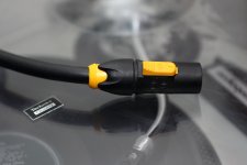
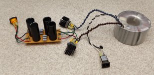
Absolutely! Here is my modular power supply - though it still needs an enclosure. Its an 18v 750VA transformer (way overkill) that I picked up cheap years ago from someone here on DIYAudio, two banks of 47,000uF caps, separated by several 0.47R 3w resistors, and terminated with a Neutrik NAC3FPX Female Chassis Mount Power 3-condutor plug. The mating male power connector is here. The power umbilical is 4-conductor 13ga wire. Another bank of caps is inside each amp.
This powers my F4, my M2, and my soon-to-be-completed Aleph-J. If I bump the voltage using my variac, it will also run my nearly-completed V-Fet2 amp.
This powers my F4, my M2, and my soon-to-be-completed Aleph-J. If I bump the voltage using my variac, it will also run my nearly-completed V-Fet2 amp.
Attachments
Last edited:
Thank so much friends for all the confirmation messages and ideas.
I actually like the 'separate case' PSU scenario, but that could prove too expensive. Maybe it's: one chasis first, and if and when a second one is made, move the PSU out, or something.
Yeah, you have pushed the AlephJ since day one we talked! LOL! I really appreciate your tenacity! Now that I have tried my speakers with the 5W of the ACÁ, the 13W of the AlephJ scare me a bit less... and the balanced option is incredibly tempting!... but it is still a fight I need to finish with myself. 😎
Obviously, the M2x has the distinct advantage of being able to be built without the unobtainium Toshiba, of which the AlephJ has 2 x 74s per channel... would that be easier to procure than the matched 170/74? The trusted eBay seller does not ship to ecuador, so I will need to find other means or find someone traveling. But that is another story.
Im still in the process of evolving ideas and reconciling budgets, so it's good to know that the same PSU would accommodate most interesting options.
Thanks,
Rafa.
I actually like the 'separate case' PSU scenario, but that could prove too expensive. Maybe it's: one chasis first, and if and when a second one is made, move the PSU out, or something.
😱 😱 😱Rafa- Yes, a PSU for the M2x could also power an Aleph J. (hint hint hint) ...
Yeah, you have pushed the AlephJ since day one we talked! LOL! I really appreciate your tenacity! Now that I have tried my speakers with the 5W of the ACÁ, the 13W of the AlephJ scare me a bit less... and the balanced option is incredibly tempting!... but it is still a fight I need to finish with myself. 😎
Obviously, the M2x has the distinct advantage of being able to be built without the unobtainium Toshiba, of which the AlephJ has 2 x 74s per channel... would that be easier to procure than the matched 170/74? The trusted eBay seller does not ship to ecuador, so I will need to find other means or find someone traveling. But that is another story.
Im still in the process of evolving ideas and reconciling budgets, so it's good to know that the same PSU would accommodate most interesting options.
Thanks,
Rafa.
Build the M2x first, knowing that the PSU and chassis is suitable for the majority of the FirstWatt DIY designs, which can be swapped in and out as you desire.
What is the minimum size chassis required. I think I could fit all the M2X components into a 3U minidissipante x 400mm, but would the heatsink be too small for some of the other Firstwatt DIY designs? A full width enclosure isn't going to work well due to lack of space around the heat sinks for them to actually work.
The 4U 300 has essentially the same heat sink capacity as the 3U 400. Actually it has a slightly better dissipation capacity.
Pass DIY Addict
Joined 2000
Paid Member
Eric - Please put a fuse on the AC after the IEC.
Yep, it's on the to-do list, Jim! All of my other projects have a fuse, this PSU was just cobbled together one afternoon - it used to live as a collection of alligator wires. It hasn't seen much action since I assembled it this way and it doesn't live on the rug where the photo was taken.
Hey friends,
For the Ishikawa board, what would you recommend for the idss of the JFETs? More leaning towards the lower values (6.5 - 7.5), towards the middle (8 - 9) (which are much harder to get) or toward the upper values (9-10).
Perhaps I'll shoot myself in the foot and buy 2 full sets (for 2 NNPP type amps). I have yet to find 4x74s for the AlephJ.
Getting the parts is a bit of a treasure hunt!, isn't it? And then you go to the DIYStore and see "only two left" on the back panel parts kit and start to sweat! This is not a hobby for the undecided or slow buyers like me! 😱
Thanks for bearing with me, best regards,
Rafa.
Well, turns out this is easier said than done 🙂 . My DVM measures the sub-1 Ohm resistors very 'generically': from 0.3 to 0.7 without a lot of consistency.... However, what I actually do is purchase ten pieces of this resistor, and then use my DVM to find the four resistors that are closest to 0.470 ohms. ...
The lowest range (automatically set) is 600Ohms with a 0.1Ohm precision and 0.5% +- 3 of error... so, yeah, basically, you know that a sub 1-Ohm resistor is "more or less in its global realm of value"... not a chance to match them.
Maybe for such low resistive values the fingers pressing against the wires may change the value? At any rate, it appears my volt meter is not up to the task of doing that sort of measurements 😡
For a small amount of builds, the price of a finer DVM may actually be more than purchasing into those $2 ~ $6 a piece for the 1% 3W resistors posted early? Has anyone tried those? NS02BR4700FE12 Vishay / Dale | Mouser
Thanks,
Rafa.
Well, turns out this is easier said than done 🙂 . My DVM measures the sub-1 Ohm resistors very 'generically': from 0.3 to 0.7 without a lot of consistency.
The lowest range (automatically set) is 600Ohms with a 0.1Ohm precision and 0.5% +- 3 of error... so, yeah, basically, you know that a sub 1-Ohm resistor is "more or less in its global realm of value"... not a chance to match them.
Maybe for such low resistive values the fingers pressing against the wires may change the value? At any rate, it appears my volt meter is not up to the task of doing that sort of measurements 😡
For a small amount of builds, the price of a finer DVM may actually be more than purchasing into those $2 ~ $6 a piece for the 1% 3W resistors posted early? Has anyone tried those? NS02BR4700FE12 Vishay / Dale | Mouser
Thanks,
Rafa.
Fresh battery, and yes funky connection, or fingers can mess it up. I lay resistor out on conconductive surface and press cable pins from multimeter against them and wait a few seconds...use consistent pressure. wait until stabilizes and is repeatable.
Russellc
I’ve had issues measuring the 3w Panasonic resistors with my DVM as well. I thought it might have to do with the length of the leads as well, since most of it gets trimmed off once soldered in. I’ll try a fresh battery too. Thanks for that tip. Ultimately I’m saving up for a nice Fluke meter though.
Last edited:
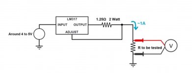
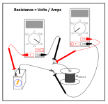
You can do it with cheap multimeter too but need build small 1A circuit or use lab bench supply 🙂
4 wire kelvin resistance measurement tutorial
4 wire kelvin resistance measurement tutorial
Attachments
Yes, as Soundhappy is telling you, you will need a four wire DMM, not a two wire, to measure things with a low resistance. I am not sure how low a price you can get a four wire DMM.
Non is Diyers 🙂 great trick!
It's Kelvin 4 wires technique but with small CCS 1A circuit ( see schematic above ) and ordinary 2 wires multimeter is OK for that
You read Voltage only ( not resistance like we ordinary do in this situation )
across the tested resistor , Voltage = Resistance for example 50 mili V = 50 mili Ohm's ( 0.05 R )
It's cheap and precise solution , equivalent of specialised and costly DMM with 4 wires option like this one Fluke
4 Wire Resistance Measurement | Kelvin connection
Yes ! Good luck for easy find of good matched source resistors pairs for the push-pull amplifier  🙂
🙂
🙂Those who are unable or unwilling to measure their resistors, can read post #479. In which member 6L6 argues that Nelson Pass's M2 circuit design works beautifully even when the components are not painstakingly matched and super precisely measured. Adopting this philosophy will save you some time and, if you were considering buying a 5.5 digit precision DVM for $175, it will save you some money too.
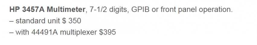
Me personally? I already own a super precise "benchtop" (not handheld) multimeter; in fact I own two, that I bought used. And they have four-point-probe "Kelvin sensing" resistance measurement, as a built in & presupplied feature. They're not especially cheap, even used. Attached below is a representative listing, from linearz.com . But hey, it's my hobby, and I can spend as much or as little as I want to spend, on tools & equipment.
_
Attachments
- Home
- Amplifiers
- Pass Labs
- The diyAudio First Watt M2x