From Amazon:
S8-Pin SOIC/SOP/SSOP to DIP Breakout Board - $6.99 US for 25 pcs:
https://amazon.com/25pcs-8-Pin-SOIC-Breakout-Board/dp/B08P5LTTD9
DIP 8 pin sockets - very nice solid milled pins - $6.99 US for 60 pcs.
https://amazon.com/gp/product/B073TW45B6/
I've used the sockets and they are very good. Just ordered the boards. The boards are a bit larger footprint than the Sparkfun, which is the size of a socket.
The sockets are so cheap at 0.12 cents each you can dedicate one to each adapter board. Just insert 8 cut off resistor or other solid wire leads of the correct diameter into a socket, drop the board on top and solder the board in place.
I posted about this previously. I don’t recall the post, but you should be able to find it my searching for me.
That said, the important point here is that the pins you select for the breakout board must be compatible with the dip connectors you select. If the pins are too small relatively then you won’t have good electrical contact. On the other hand if they are too large in diameter relatively then the pins won’t fit in the connectors. CHECK YOUR DATA SHEETS.
That said, the important point here is that the pins you select for the breakout board must be compatible with the dip connectors you select. If the pins are too small relatively then you won’t have good electrical contact. On the other hand if they are too large in diameter relatively then the pins won’t fit in the connectors. CHECK YOUR DATA SHEETS.
The DIP sockets linked to above seem to meet the standard of accepting .015” - .025” diameter leads.
Dale RN55, RN60 and RN65 resistor leads are all .025". RN50 leads are .016". Vishay MBB and SFR series are .023". So it seems most "quarter watt" size and even "eighth watt" size leftover lead cutoffs from resistors should work.
Dale RN55, RN60 and RN65 resistor leads are all .025". RN50 leads are .016". Vishay MBB and SFR series are .023". So it seems most "quarter watt" size and even "eighth watt" size leftover lead cutoffs from resistors should work.
You could also just solder the pins (resistors cut off) to the socket so all are soldered at the end?
The sockets I looked at was TE-Connectivity (think that was the name) and they came in a 60 pcs packet at about $100. I had some bad experience with sockets that only "bite" a few times after an opamp has been inserted and taken out again. After then it felt like a "loose fit"....and it was the "good type" of socket like the ones from Amazon. Therefor I decided to look at some expensive ones....but just before I ordered them I changed my mind and said to myself.....I just solder it in 🙂 ....even the expensive opamps.....
The sockets I looked at was TE-Connectivity (think that was the name) and they came in a 60 pcs packet at about $100. I had some bad experience with sockets that only "bite" a few times after an opamp has been inserted and taken out again. After then it felt like a "loose fit"....and it was the "good type" of socket like the ones from Amazon. Therefor I decided to look at some expensive ones....but just before I ordered them I changed my mind and said to myself.....I just solder it in 🙂 ....even the expensive opamps.....
I used quarter watt resistors to create the legs/leads for the twelve SOIC-to-DIP adapters used in the experiment described in post #4755.
When you buy qty=100, quarter watt resistors are cheap, and if you bend one lead 180 degrees so the resistor is in a Vertical Insertion position, its legs slide into adjacent holes on the adapter board and the resistor body prevents them from escaping by sliding out. So it's easy to get the leads into exactly the position you want, for soldering. Then clip off the resistor body on the top side: done!
When you buy qty=100, quarter watt resistors are cheap, and if you bend one lead 180 degrees so the resistor is in a Vertical Insertion position, its legs slide into adjacent holes on the adapter board and the resistor body prevents them from escaping by sliding out. So it's easy to get the leads into exactly the position you want, for soldering. Then clip off the resistor body on the top side: done!
After trying three different email addresses to no response, I called Cinemag and they readily took my order. 7-8 week lead time for a pair of CMOQ-4HPC transformers for the M2X. They are doing a large batch of them for a client and added my order to the production lot. It would be a good time for anyone else wanting to try some high-nickel transformers to piggy back on this lot.
these work great—I think you can find them a lot of places—Mouser carries them—not sure about the EU...
SparkFun SOIC to DIP Adapter - 8-Pin - BOB-13655 - SparkFun Electronics
This might be a good place to ask. I have the spark fun boards and was going to use them on the Salas DCG3. It turned out that the rotation of the chip was the wrong direction from what I needed on the project (CW/CCW). Got new adaptors from eBay.
I fixed the problem but I don't even know how to differentiate between the two other than looking at the dots on the board and checking it against a picture like Salas posted or to look at the circuitry.
Am I missing something?
Thanks,
Don
After trying three different email addresses to no response, I called Cinemag and they readily took my order. 7-8 week lead time for a pair of CMOQ-4HPC transformers for the M2X. They are doing a large batch of them for a client and added my order to the production lot. It would be a good time for anyone else wanting to try some high-nickel transformers to piggy back on this lot.
What do you think the difference will be. I know this was discussed at the time of original design of the M2. I believe this was NP's first choice.
Thanks,
Don
The CMOQ-4 comes in -4L and -4H designs. The CMOQ-4L uses 50/50 nickel and iron laminations. The CMOQ-4H is the “high nickel” variant using 80/20 nickel/iron. Iron is less expensive than nickel and does not saturate as easily as nickel. Nickel has higher relative permeability than iron, which means more inductance per turn vs a coil of the same geometry using iron laminations instead.
I’ve compared iron laminations vs amorphous strip-wound output transformers (metglass) and preferred the amorphous. My impression was that of less transformer coloration or more clarity. I’m hoping a high nickel core will impart some of the same vs the edcore unit (currently being shipped).
Here’s the tech specs of the Cinemag unit:
https://cinemag.biz/output/PDF/CMOQ-4.pdf
Thanks for the Cinemag link!
Their transformer datasheet has a little footnote "See application note AN-102" for information about amplifiers driving the transformer primary.
And Cinemag's AN-102 appnote recommends using the HA-5002 integrated circuit to drive the transformer primary.
Guess what? The M2x already does use an HA-5002 IC to drive the (Edcor) transformer primary! Take a look at the schematic [attached to post #1] of the Norwood daughter card. There it is! U5 = HA5002 right on the schematic.
If you yanked out the Edcor and dropped in a Cinemag transformer, you certainly can drive it just as Cinemag recommends. Bolt in your Norwood daughter cards and have a great time.

IPS6 should also be able to drive Cinemag?
I have not looked into the details. Are Cinemag plug compatible with Edcor at PCB-level?
Have no plans to change......so just interest.
Those high permeability cores goes quite easy into saturation?
So even more care should be taken to avoid DC?
I have not looked into the details. Are Cinemag plug compatible with Edcor at PCB-level?
Have no plans to change......so just interest.
Those high permeability cores goes quite easy into saturation?
So even more care should be taken to avoid DC?
I received some components today for IPS7 and Cedarburg input boards. A surprise again that still some silicon is "Made in USA".
The LT1028 opamp has printed that they are made "locally"?
In California maybe?
The two other opams are from Philippines.
I wonder why I play around with opamps now I have the IPS6 and Norwoods. Seems they are still considered the "reference"?
Can Cedarburg compete with that?
The LT1028 opamp has printed that they are made "locally"?
In California maybe?
The two other opams are from Philippines.
I wonder why I play around with opamps now I have the IPS6 and Norwoods. Seems they are still considered the "reference"?
Can Cedarburg compete with that?
Attachments
Maybe if you built another pair of IPS6 boards, but this time using J112 transistors instead of J113 transistors,
and maybe if you measured a population of 100 J112 units to extract your two super-duper-amazingly-matched pairs,
maybe THAT would be the one which sounds best, to you. All of your hours of toil and effort on the project, all of the money and emotion which you have invested, may influence your listening evaluation: the "proud parent" effect. The final result may be overwhelmingly preferable, to you.
You could tinker around with other values for the "100 pF" compensation capacitor; the one chosen by YOU will probably sound better to you than the standard value everyone else uses.
And finally, you could experiment with setting the IPS6 trimmer potentiometer "by ear" instead of by reading a millivoltmeter. Maybe you'll discover that (1/2 turn clockwise) beyond the standard setting, gives a sonic presentation that you like even more. You'll never know until you try.
If we could compensate for the psychological factor when listening then it could be boring.....maybe no need for that many input boards......
What I think is that IPS6 is the one that generates most "white noise". Don't know if there is a scientific reason behind this. I would think that the high bias current and temperature would generate more noise?
My only measurement is by ear up to tweeter to evaluate the "sshhhyyy" noise. Will check again when I shift to a IPS7 or Cedarburg.
The BAS34 diodes in Cedarburg circuit are there to protect the input of AD797 during power on/off?
I assume that a standard diode like 1N4148 could do the job also?
Think I got those in "bulks" so I did not need to buy 2 at a time each time.....
Do you all use BAS34?
I assume that a standard diode like 1N4148 could do the job also?
Think I got those in "bulks" so I did not need to buy 2 at a time each time.....
Do you all use BAS34?
Buy them from the same distributor, at the same time, when you buy the AD797. Or are you planning to substitute a different opamp for the '797, one that you bought previously and have been saving in your parts box?
How do we get the BOM amp board parts list updated?
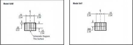
The 5k trimmer part number for Mouser is incorrect - does not have the pins in a single line, they are offset - part#858-64WR5KLF
According to the datasheet "64W" is offset and "64Y" is in-line pins. Snip from datasheet is below to confirm. The correct part# should be "858-64YR5KLF"
also - I missed the suggestion to change R6 to 37k and RV1 to 20k, went by the BOM and ordered before carefully reading all the notes in the zip file - my bad! Would it be sacrilege to add these as "alternative R6 and RV1 - see notes" on the BOM?
I guess it's good the trimmer was wrong (maybe), because I would have to order again anyway, and now I'll order the 20k version and revised R6.
These alternate part numbers are:
KOA Spear 37k - "660-MF1/4DCT52R3602F"
Alt. RV! - "858-64YR20KLF"
Attachments
Buy them from the same distributor, at the same time, when you buy the AD797. Or are you planning to substitute a different opamp for the '797, one that you bought previously and have been saving in your parts box?
I could not find BAS34 at the place I got the AD797 (at RS). I also still need the 30V zeners and probably the 4.7n COG. One of the problems is "lost overview" of components at the "shelf". I need an Excel of all my components as I tent to buy many of "standard" components to get price down. But it requires I can remember what I have.....or find them easy.
I will find the BAS34 somewhere.....
I wondered why this company can sell a mic-kit for $30 incl. two original AD797?
Ad797 Mic preamp Kit
- Home
- Amplifiers
- Pass Labs
- The diyAudio First Watt M2x