Hi Katie,
Try to swap the transformer or the PSU...
maybe it is over voltage...
I've try similar with BJT output & a little different PSU brings different bias, different stability too
Then measured again, check if the voltage is similar with the normal one
John
Try to swap the transformer or the PSU...
maybe it is over voltage...
I've try similar with BJT output & a little different PSU brings different bias, different stability too
Then measured again, check if the voltage is similar with the normal one
John
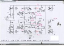
while you're in there measure the voltages at the base of tr1 (or across R10) and tr3 (or across R12) as well.
fwiw it were my amp i'd just snip the leads of TR4 and TR5 near the 90 degree bends i/o desoldering them off the pcb. Easy job to resolder them after. This also makes it easy to check that TR4,TR5 and TR2 are properly insulated from the heatsink. But your decision.
fwiw it were my amp i'd just snip the leads of TR4 and TR5 near the 90 degree bends i/o desoldering them off the pcb. Easy job to resolder them after. This also makes it easy to check that TR4,TR5 and TR2 are properly insulated from the heatsink. But your decision.
Last edited:
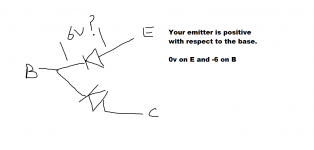
You can't have a 6 volt differential across a B-E junction (TR5) unless it is reverse biased. Your readings show its "not" (emitter positive with respect to base) which leaves the possibility that TR5 isn't a PNP, or that its faulty or fitted incorrectly.
No mystery 😀 There is a definite problem with TR5, be it incorrect polarity device, a faulty device or an incorrectly fitted device. Whether there are other problems remains to be seen.
No mystery 😀 There is a definite problem with TR5, be it incorrect polarity device, a faulty device or an incorrectly fitted device. Whether there are other problems remains to be seen.
agree but it apparently tested out above ok ?
agree but it apparently tested out above ok ?
Not possible 🙂
Its the same as saying "I have 6 volts across a forward biased silicon diode"... but it checks OK. There is one more possibility, but I would doubt this, and that is that the whole area around the transistor is oscillating at RF which would make all DC readings invalid. One quick check with a scope would prove/disprove that though... as would a well placed finger around that area.
I'll see if I can find another TR5. OK I've got one coming on Wednesday from LittleDiode.com
Last edited:
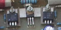
are you sure they are installed the same way on both channels. Look at the middle transistor in each of these images carefully.
edit: also shouldn't there be an insulator?
Tony.
edit: also shouldn't there be an insulator?
Tony.
Attachments

Last edited:
Yep, they are both identical. The faulty amp did work.
The MJE340 in the centre, TR2 is mounted upside down and has a fibre washer insulating the TR from the nut.
The MJE340 in the centre, TR2 is mounted upside down and has a fibre washer insulating the TR from the nut.
Ok the one on the left looks like it is mounted conventionally. I guess the pad is smaller than the other one?
Tony.
Tony.
0.9 volts assuming its accurate is too high. Without being familiar with your meter I wouldn't like to say how that should be interpreted. The raw numbers say something is not right.
Work to what you can see is definitely wrong, which is the 6 volts we had above.
Work to what you can see is definitely wrong, which is the 6 volts we had above.
I've just done diode tests on both TR4 and TR5 and they both measure about 0.9V BE and BC.
Try measuring the voltage across the B-E junction of TR5 in the amplifier and confirm that the 0v and -6v results you obtained previously translate into a measure 6 volts across the junction.
I think one of my multimeter diode tests must be failing.
Just tested them again with a Fluke and all junctions are 0.6V.
Just tested them again with a Fluke and all junctions are 0.6V.
- Status
- Not open for further replies.
- Home
- Amplifiers
- Solid State
- The David N.J.White 100W MOSFET amplifier