Well I changed the pots and it's got worse. I've now got -12V DC on the output. So its not full rail DC indicating a failed output device.
Although I've got no white smoke and nothing has catastrophically failed - YET. I'm loathe to keep power on this for too long for measurements.
I only build these, I don't design them so any pointers as to which area I should target first with the meter would be much appreciated.
I only build these, I don't design them so any pointers as to which area I should target first with the meter would be much appreciated.
Maybe they have failed in infant mortality period, maybe they were damaged by static, maybe they were damaged by soldering.
Before you start measure the DC voltages at several points on the good and bad boards and compare, that may give you a clue.
Before you start measure the DC voltages at several points on the good and bad boards and compare, that may give you a clue.
I'm not too comfortable leaving power applied for too long. Where would you start.
T1 and T3 are right buggers to change as they are moulded together with the LEDs.
T1 and T3 are right buggers to change as they are moulded together with the LEDs.
Last edited:
I would check out the op-amp and its zener supplies. -12V on the output could indicate a DC bias on the op amp.
This is where a current limited dual rail bench supply can come in very handy!
This is where a current limited dual rail bench supply can come in very handy!
Do as AndrewT always suggests and get a light bulb tester 🙂
Also have a good look at R2 and make sure there are no problems there. A poor joint may be causing your output offset.
Tony.
Also have a good look at R2 and make sure there are no problems there. A poor joint may be causing your output offset.
Tony.
WinterMute, this one is well passed the stage of testing with mains bulb tester. It's operating but not quite as expected.
Well you said you were worried about running it for any length of time, I took that to mean you were worried you might fry something, so a lightbulb tester seemed appropriate 🙂
Tony.
Tony.
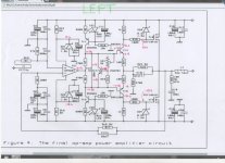
If you like/have time, maybe annotate the schematic above with measured voltages and post it here,
Its then almost certain that someone here will be able to help you to troubleshoot.
Its then almost certain that someone here will be able to help you to troubleshoot.
OK I've taken some readings ?
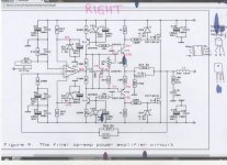
Now, if you recall, the LH amp seems OK and the RH amp is at fault.
To my novice brain I would suspect the op-amp.
On the working amp everything is stable and the ouput of the op-amp is a steady 0.19V.
On the faulty amp the output of the op-amp is unstable and seems to keep climbing to round the 3.5V mark. Differences in readings along a pcb trace are due to the voltages changing as I move the MM probe around.
Both PCBs are identical and the components are identical.
Attachments
Last edited:
OK I've swapped the op-amps over and there is no change to the voltages.
Both amps are exactly as in Post #35.
Both amps are exactly as in Post #35.
negative feedback in a faulty circuit can make things confusing.
are you sure both output mosfets are good?
how are you measuring bias current?
mlloyd1
are you sure both output mosfets are good?
how are you measuring bias current?
mlloyd1
Please check the voltage on the base of TR1 and TR3 for both channels and report the result 🙂 edit: just noticed RichieBoy suggested replacing them.... based on the voltage differences you are seeing I'm suspicious of them... could also be a bad joint on R10 or R12 or possibly bad C11/C13.
Tony.
Tony.
Last edited:
OK.
The results are different as this is a dual mono construction, ie two separate PSUs.
LH Amp Rails +/- 50.8V
TR1 and TR3 bases are both identical at +/- 48.8V
RH Amp Rails +/- 53.7V
TR1 and TR3 bases are both identical at +/- 51.6V
The results are different as this is a dual mono construction, ie two separate PSUs.
LH Amp Rails +/- 50.8V
TR1 and TR3 bases are both identical at +/- 48.8V
RH Amp Rails +/- 53.7V
TR1 and TR3 bases are both identical at +/- 51.6V
- Status
- Not open for further replies.
- Home
- Amplifiers
- Solid State
- The David N.J.White 100W MOSFET amplifier