I wonder if going from 5x3 to 6x3 would be a good improvement for my planned use with a JBL2445 from 500 Hz up. I have not yet printed all cells and the adapter. There are small gaps at the throat section due to the arrangement of cells in space (touching with corners of the upper and lower cells only). These were normally filled or deformed to have no gap there?
For home use I can't see needing more than 15 cells.
Not sure what you mean about the throat gaps.
Not sure what you mean about the throat gaps.
Pano,For home use I can't see needing more than 15 cells.
is it correct to assume that the distribution pattern angles are proportional to the number of (square) cells in that certain plane? So, if the horn shall get 20 (5 x 4) cells instead of 15, the vertical distribution angle is wider?
Best regards!
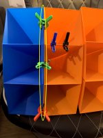
Another triplet glued together. Tomorrow, the last one will be made. Then, mouth spacers and edge stiffeners will be printed and it will be time for casting.
Ideally the throat cells would be deformed to have no gap, a "knife edge", as filling alone would cause a reflection (echo) back into the driver, causing some "chatter".There are small gaps at the throat section due to the arrangement of cells in space (touching with corners of the upper and lower cells only). These were normally filled or deformed to have no gap there?
As far as I'm concerned, the allure of the multi-cell is the tight pattern control they achieve, using more cells than the area of high frequency coverage desired just makes for more room reflections.
Of course, if you like room reflections, the more cells the better...
Art
Thanks. I wish I was better at 3D modeling, so that the slight deformation would be also printed. I will push the sides together as good as possible and fill the gaps if necessary. If the prototype will be successful, I may get into exploring the full possibilities of 3D printing. Joseph Crowe made his multicell optimized, but his design would not be easily replicable with a FDM printer. Maybe using a slightly different approach and printing in parts would work. Challenge accepted🙂
In practice, yes. More cells means a wider angle. But that should be because manufacturers tended to keep the cell mouth the same size (for a given cut-off) and just stack more together.So, if the horn shall get 20 (5 x 4) cells instead of 15, the vertical distribution angle is wider?
One would suppose that horns of the same size and shape could be built of anything from 4 to 36 cells with similar coverage, as long as the cell size changed to fit within the overall size and shape of the horn.
A larger cell mouth is going to start beaming at a lower frequency than a small cell. So a small cell ought to be better. But the design details of how the cell wavefronts combine are beyond my knowledge. How small is small enough for a cell? And at what given listening distance? Running simulations of a single cell is easy enough, but what really happens when they are combined?
Also, see Art's reply above.
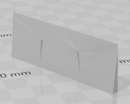
The last part of the cells finished printing a few minutes ago. I decided to use a 3D printed spacer on the throat end. It will extend slightly to the throad adapter to form an edge instead of a flat area. The rendering gives a knife sharp edge, the real product is limited by printer resolution. With a bit of putty and sanding, the transition can be made quite smooth.
The throat adapter is my next problem. Actually a set of problems.
1) The dimensions will be certainly different in reality from the 3D model (that will be handled by measuring when I glue everything together).
2) If I understand it correctly, it should be exponentially changing area from a circle to a rectangle with the same flare rate as the cells. That is very hard for me to create in 3D, but will be possible if I can find a solution for the next problems.
3) Also, the throat part of the adapter is flat and the area where the cell throats join is roughly rectangular cutout of a sphere. How would one define this? What area on the throat side should I consider for calculation and when calculated in Hornresp, and how to use the calculated length?
4) When I have the correct length at the correct areas, what should be the shape of the transition? My math is not good enough to define such a shape. One of the ideas is that I could make a square throat to rectangle mouth adapter and morph from a circle to a square in an exponential rate, would that work? That should be doable with my skills. The total length of the adapter would be divided to two parts - circle to square and square to (a flat) rectangle. The interface to the cells would expand the top and bottom conically (over a relatively short distance) so that it can be glued to the cells.
So any input on this will be very welcome. If the final product will be worth it, I will share the models of everything so that everyone can built his own.
The second version would use different cell shapes at the mouth so that the spacers would not be necessary. Pentagon/hexagon crossection cell combination would also be relatively easy to create in 3D with the help of Hornresp for and unorthodox look and shorter necessary adapter length. Maybe a project for long winter evenings🙂
Attachments

Admittedly, I just don't get why there are these gaps in the vertical intersections that need to be filled?!? Why do they appear if you first stack cells with square cross sections vertically? What would happen if you'd build a 3 x 3 multicell and decide to glue the horizontal lines first? Or, with your and the original 5 x 3 design, if the five horizontal cells were glued first?
After all, I had a close look at the original wooden construction at the very beginning, and these gaps appear to be there also?!?
Best regards!
After all, I had a close look at the original wooden construction at the very beginning, and these gaps appear to be there also?!?
Best regards!
Hi GM,
32 cell Jensen ?
Here's your thread with pics ( click the pic ).
https://www.diyaudio.com/forums/multi-way/173240-jensen-32-cell-horn-2.html
🙂
Greets!
Interesting! Thanks! Was pretty sure I'd posted pics somewhere, but Google returned nothing and neither did Hostboard and didn't think to try here. 😡 🙁
Well, I got nothing then since the tubes were obviously in a W.E. or similar 'muffler'/adapter, which the Jensen clearly doesn't have unless another Jensen I don't recall.
Ideally the throat cells would be deformed to have no gap, a "knife edge".........As far as I'm concerned, the allure of the multi-cell is the tight pattern control they achieve, using more cells than the area of high frequency coverage desired just makes for more room reflections.
Of course, if you like room reflections, the more cells the better...
Art
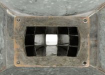
Right and clearly visible in this throat: Horn Speaker For Sale at 1stDibs
Agreed, though in home use they do well toe'd in.
That said, they often ideally need to be turned 90 deg when appropriate, but I only know one owner that agrees and periodically [re] posts it to 'deaf' ears since "BY GOD if they were meant to, then they would have designed/installed them that way!"
Surprisingly, many owners do. 🙁
But the design details of how the cell wavefronts combine are beyond my knowledge. How small is small enough for a cell? And at what given listening distance?
No different than Bozak's B200XA bunch of cone tweeters to mimic a multi-cell, which was later replaced with the first line array I'd seen: http://www.hifilit.com/Bozak/brown-3.jpg
http://www.hifilit.com/Bozak/brown-4.jpg
http://www.hifilit.com/Bozak/1968-4.jpg
Depends on the design goals, I've seen pics of some multi-cells that appear to be tiny versions of the 32 cell [though not necessarily 32] except ~811 size.
Assuming it was based on early cinema design, the first row of seats was 45 ft 'as the Crow flies' and of course firing through a screen to further 'smear' the distance, so not what you call a near-field device and even the later sectoral horns was 25 ft. for small cinema, prosound apps.
That said, I've seen pics of the multi-cells as pretty close up studio monitors, so go figure.
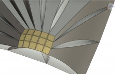
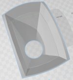
Kay Pirinha, here is a view of the throat area in my 3D model. The squares at the front and back create a sort of spherical surface, that is why there are gaps.
GM, on the pictures you linked, it looks like the thin walls are deformed to touch as much as possible and the corners are filled with solder. This could be solved in 3D by slighty deforming the cells at both ends so that no gaps after gluing appear. Would that be worth it? That would lead to 4 different kinds of cells if I am counting correctly (corners, upper+lower outer, middle, left+right outer). I am not sure if these could be still printed in vase mode though. The middle ones most probably could.
GM, on the pictures you linked, it looks like the thin walls are deformed to touch as much as possible and the corners are filled with solder. This could be solved in 3D by slighty deforming the cells at both ends so that no gaps after gluing appear. Would that be worth it? That would lead to 4 different kinds of cells if I am counting correctly (corners, upper+lower outer, middle, left+right outer). I am not sure if these could be still printed in vase mode though. The middle ones most probably could.
Attachments
Pelanj, those are looking very good. I like the jolly colors.  Throat adapters have been taking up a large portion of my thoughts lately. I'll get some coffee and share my thoughts later.
Throat adapters have been taking up a large portion of my thoughts lately. I'll get some coffee and share my thoughts later.This is the best profile I was able to come up with so far. Gradually changing from circle to a spherical surface profile. The little step there is to compensate for wall thickness. I am actually considering to split this into two like in the old designs, so that I can get my fingers, putty and a file to the throat area to make everything as smooth as possible.
Attachments
Been following your progress with interest - I finally broke down and bought a 3d printer and now have to find time to assemble it. Then begin the learning curve to model/print.
I don't know if this is any help but I found this 3d model a few years ago that could be printed for the altec 30166 throat that would fit the 1505 I believe.
Altec 30166 Throat | 3D Warehouse
Also earlier in post #366, I linked an article from the 40s about multicell construction and as Pano astutely pointed out in the next post - one wall of the cells constructed in that article were "slightly wider so that the whole thing will fit together without spacers between the cells". Might could help at the throat to prevent gaps.
Thanks Tom, I had forgotten about that. Going back and reading this thread again would be a good idea. 🙂
Pelanj that adapter looks good. One would suppose that using the same expansion profile in the throat as you have in the cells would be a good idea. But since you have to transition from round to rectangular, what you gonna do? The throat adapters on the Altec horns seem short and fat compared to other brands. My adapter on the 803 stays at 1.4" in the vertical, while expanding horizontally to double that width. It looks basically conical, but it might be expo or hyper, it's difficult to tell with that shape change over a short distance.
A smooth regular expansion and shape change seem to be what most builders do. How much does it matter? How well does the HF coming from the driver exit spread across the cell throats? The spread isn't perfect, there is some beaming and HF fall-off on the outer cells. This is certainly an area for thought and research.
- Home
- Loudspeakers
- Multi-Way
- The construction of a multicell horn