Some of you asked for schematics and details. Everything, including CAD files and SPICE simulations is in this Github repo. Keep in mind that this is a work in progress and there might still be bugs to work out. Preliminary tests have been successful so far, but proceed with caution if you want to use the design!
https://github.com/prydin/the-bog-standard
If you see something amiss, please raise an issue in the repo, or even better, fix it and submit a PR. 🙂
https://github.com/prydin/the-bog-standard
If you see something amiss, please raise an issue in the repo, or even better, fix it and submit a PR. 🙂

@njswede
Thanks for your work.
Interesting to see what the end result will be.
Already you have a good amplifier - Bog Standard Amp.
Thanks for your work.
Interesting to see what the end result will be.
Already you have a good amplifier - Bog Standard Amp.
Thank YOU for the kind words. I’m having a blast experimenting with this and it would be a great extra bonus if someone found it useful.

Yes, that is good.An LED matches well with VFets.
View attachment 1426976
So you say it matches well with a red LED.
Nice.
You can reduce your component count by dropping the two transistors in the CCS for the input stage.
This will balance the H3 dominant output of the LTP with a little more H2. Supply the LTP with two resistors in series, with a 47uF from the midpoint to ground for smoothing. More H2 will add a touch of warmth, making the amp sound very slightly tubey.
Then you can drop the gate drivers. You should use about 10mA through the VAS stage, two comp IRF240/9240 gates are easy to drive and you are not moving 200KHz.
Finally, the bias generator is best used with another small mosfet with an identical tempco. The suggestions using bipolars are more complex, and the tempco will not identically match.
HD
Adding a second diode-coupled transistor for thermal compensation doesn't seem necessary from what I've seen so far. Mounting Q7 on the same heatsink as the output devices seems to makes it fairly thermally stable. It does briefly spike to about 150-170mA bias current on startup when everything is cold, but after a minute or so, it settles nicely at 100mA. Once the MOSFETs warm up, they seem to have roughly the same tempco as the VBE, since the bias current only varies by about 10% even if I crank up the volume a lot. This is with a proper heat sink fitted. When I ran it with just a piece of sheet metal, it had a very significant negative tempco.
I set it up to run one channel through the version we came up with together and one through the original design in the first post. It's night and day, especially on the level of detail and high frequencies.
Thanks everyone who helped guiding me!
Thanks everyone who helped guiding me!
I'm still ruminating on some contrarian Le Monstre / ACA Mini -like topologies, taking local feedbacks from source resistors in the output stage.You can reduce your component count by dropping the two transistors in the CCS for the input stage.
This will balance the H3 dominant output of the LTP with a little more H2. Supply the LTP with two resistors in series, with a 47uF from the midpoint to ground for smoothing. More H2 will add a touch of warmth, making the amp sound very slightly tubey.
Apart from source degeneration, taking further steps to linearise the output MOSFETs individually is rare. But I think it could make them perform a bit more like single-ended designs. One general "push-pull problem" I see is that the cancellation of harmonics is uncontrolled. There's nothing to prevent a polarity reversal / "zero crossing" of harmonics.
E.g.: the IRFP240 generates some H2, gradually sloping UP in amplitude. The IRFP9240 generates a similar amount of H2, sloping DOWN. For a brief moment there is perfect cancellation as the amplitudes are equal. Then the amplitude bounces back. And the overall envelope of this H2 modulation is unrelated to the sine wave that it's a harmonic of, but may be influenced by something else like a bass line playing at other frequencies.
A related curiosity is that, in some simulations, MOSFET source resistors showed around ~6% HD in an open loop test. Of course tying the drains together reduced the combined distortion to below 1%, but how steady is that in response to DC (low freq.) offsets? At the same time, the speaker is loading down the output by a slightly-mysterious amount, while the NFB is trying to sense the voltage. So there's a lot going on. This makes me wonder if that's the secret sauce behind Nch-Nch designs, or single ended, where the CCS load does not cancel anything. Food for thought.
I’ll gladly admit that I didn’t understand much or that post, especially not above the paragraph.One general "push-pull problem" I see is that the cancellation of harmonics is uncontrolled. There's nothing to prevent a polarity reversal / "zero crossing" of harmonics
I can attach a sketch, when I'm not on the go. Maybe the example wasn't clear? Rephrasing: the IRFP(9)240 transistors both generate distortion, but in opposite polarity, so the combined total is smaller than either on its own. That's the idea anyway. However, due to real-world modulation they may switch places:I’ll gladly admit that I didn’t understand much or that post, especially not above the paragraph.
IRFP9240: reduces from 1% H2 ---> to 0.9%,
IRFP240: increases from 0.9% H2 ---> to 1%
Somewhere in the middle, on a time scale, there is a perfect null: 0.95% - 0.95% = 0.0000...%.
For multi-tones, e.g. 100Hz and 1kHz, the 2nd harmonic @ 2kHz would have a 100Hz beat frequency, aka amplitude modulation. One funny thing is, by slight de-tuning or adding a small amount of even HD at the input, the dynamic range of the beats (max-dB minus min-dB) could be reduced.
So how does this apply to my amplifier design? Do you have any improvements to suggest?
That is what 'I' was refering to!Well you could try AKSA's suggestion with
Aha!
Oh my goodness.
See here, crazy stuff.. :)with the resistor 'tail' for the input LTP. And you could vary the length of the tail by using a string of resistors and compare the sound with the capacitor connected at different voltage points.
ps. OStripper tried to simulate it but used a very small cap, C1 (C5 0,1 uF in his schematics), I think it should be much larger, unfortunately I never tried this circuit in reality so I don't know the result.. :(
Hi everybody,
I thought I would start a new thread regarding a perhaps new(?) idea how to load the LTP stage.
As we know there are people who prefers a CCS circuit at the tail of the LTP while others would choose a simple resistor, both have their pros and cons objectively/subjectively.
Having thought about it I came up for some time ago with an idea where we might perhaps enjoy the best of both, so I came up with the following circuit attached as a picture.
With the circuit as shown in the attachment we can enjoy both high PSRR and still get the 'quality' of a resistor as a current...
- UniQ
- Replies: 5
- Forum: Solid State
Last edited:
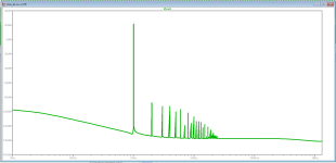
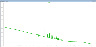
I tried to replace the CCS with a simple resistor for the LTP and got some interesting results. The total THD is about the same, but there's a significant (albeit probably inaudible) difference in H3. It's a fair bit lower without the CCS. The quiescent current through the LTP is about 1.4mA in both cases.
Conventional wisdom seems to be that a CCS improves OLG and therefore helps smoothing out crossover distortion, but I guess there's something else going on here.
Conventional wisdom seems to be that a CCS improves OLG and therefore helps smoothing out crossover distortion, but I guess there's something else going on here.
Attachments
- Home
- Amplifiers
- Solid State
- "The Bog Standard" - A good enough amplifier for the rest of us