Do you mean the tail current source? Replacing that with a resistor doesn't reduce loop gain, but it could make the comparison between the input and feedback signals less accurate. You can always get distortion compensation effects: make something worse and get a better overall result for some specific input signal because distortion products happen to cancel. Sometimes you can even do it predictably.
Yes, I mean tail current. And it’s the current mirror that improves OLG. Impressive how many mistakes I can make in one post. 😀
That's a good catch with the current mirror. That seems to add redundancy: current in = current out, so it kind-of defeats the idea behind the tail mods.
On the other hand, a resistor-loaded LTP would strongly rely on the character of the tail. If the tail uses a 'strong' CCS with output resistance in the mega-ohm range, harmonics 2, 4 etc, are strongly cancelled. Allowing additional current to flow through a parallel resistance would re-introduce those harmonics in a controlled manner.
That said, I'm wary of introducing harmonics for the sake cancelling-out something else downstream. Masking, yes. But with complex signals every stage simply must introduce some inter-modulation between the different frequency components, and so those side-bands just keep multiplying through each piece of silicon.
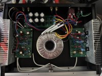
I built the second channel today and took a little more care when it came to component matching. THD is 0.0047%, which is pretty much the loopback THD of my crappy sound card. I'm fairly confident I can get this to >0.001% with a proper power supply and better test equipment.
The slew rate comes in at a healthy 27V/us at +-29V supplies right below clipping. +-(29V happens to be the most I can reliably get out of my lab supply). I'm planning on running it on 37-40V rails, so I might be able to squeeze out some more slew rate. 27V/us is already overkill in my book.
I should get a case for it this week so we can check out the final result. I'm very pleased with what I'm seeing and HEARING so far.

I've finally gotten round to drawing a diagram....I’ll gladly admit that I didn’t understand much or that post, especially not above the paragraph.
Top:
Distortion of low frequency A is exaggerated for visibility.
Below that is what I call harmonic number 3. So I'm going with the convention that the fundamental starts at 1, not 0.
Below that is the envelope of a higher frequency, B, which is starting to get modulated. As A approaches clipping, B's gain goes down, but it's asymmetric: one half cycle gets squished as it tries to clip harder, while the other half returns closer to centre.
So if we look at the harmonic content of B, over time, we can see H2 undulating up and down in amplitude.
Obviously the total amplitude of B is getting modulated by maybe 3dB (and in normal usage, far less). However, the harmonics of B are heavily modulated: you basically get a divide-by-zero error when calculating the dynamic range of the H2 "ringing".
So this all ties in with adding a small amount of H2 at the input stage, to make the amplitude more stable. What that should do is shift the balance point, so H2 no longer goes to zero at 0Vout, but gets offset by some amount, similar to crossover distortion.
Looking at the mechanism of distortion in relation to the transfer function that created it ultimately helps to understand the basics to interpret the frequency spectra existing in the frequency domain. It's a good exercise.I've finally gotten round to drawing a diagram....
View attachment 1432382
Top:
Distortion of low frequency A is exaggerated for visibility.
Below that is what I call harmonic number 3. So I'm going with the convention that the fundamental starts at 1, not 0.
Below that is the envelope of a higher frequency, B, which is starting to get modulated. As A approaches clipping, B's gain goes down, but it's asymmetric: one half cycle gets squished as it tries to clip harder, while the other half returns closer to centre.
So if we look at the harmonic content of B, over time, we can see H2 undulating up and down in amplitude.
Obviously the total amplitude of B is getting modulated by maybe 3dB (and in normal usage, far less). However, the harmonics of B are heavily modulated: you basically get a divide-by-zero error when calculating the dynamic range of the H2 "ringing".
So this all ties in with adding a small amount of H2 at the input stage, to make the amplitude more stable. What that should do is shift the balance point, so H2 no longer goes to zero at 0Vout, but gets offset by some amount, similar to crossover distortion.

It works really well so far. The only issue is that the BD139 /140 pair in the VAS get really hot. I think they're dissipating about 500mW, so I should have put them on a heatsink. I might reduce the current a little bit or see if I can squeeze in a little heatsink.
THD is 0.005%, which is at the limit of what my soundcard can measure.
I had to make some compromises to fit everything in this small case, but there’s no audible hum, so it can’t be that terrible.
THD is 0.005%, which is at the limit of what my soundcard can measure.
I had to make some compromises to fit everything in this small case, but there’s no audible hum, so it can’t be that terrible.
Attachments
Based on the schematics in #1, the VAS only works at 7mA. Usually, I use TO-92 transistor at this position without the problem.The only issue is that the BD139 /140 pair in the VAS get really hot.
BTW, the C4 in #1 is slightly reverse biased. The positive lead should face to ground, in theory. It might not matter in reality.
It's been heavily modified since then. 500mA through a BD139/140 without a heatsink SHOULD be OK, but it feels pretty hot. Not like burning my finger to a crisp hot, but unpleasant to touch for an extended period of time. I might just find a little piece of sheet metal to attach to it to get some more surface area to dissipate the heat. Latest version of the schematic below. And a minor correction: They should be dissipating about 400mW.

They are fine. They are rated 1.25W naked. You got 3x times headroom.They should be dissipating about 400mW.
One suggestion, to reject hum properly, these 2 grounds marked below should be the signal ground, not the power ground. The input jack should be isolated from the chassis. Bridge 2 grounds with a 10 Ohm resistor on the amp board.
Last edited:
Thanks. There’s really no audible hum and it measures at about -90dB. But I’m all for following sound design practices!
Here is the best practice that I could find online.
https://hifisonix.com/wp-content/uploads/2019/02/Ground-Loops.pdf

https://hifisonix.com/wp-content/uploads/2019/02/Ground-Loops.pdf
LOL! I let the magic smoke out. Can anyone see my mistake? This is my VAS. There's about 11mA through it (not even sure that's relevant). I tested driving the amplifier into clipping (using the drum beats from Blue Monday, what else?) and something popped. I haven't torn it apart yet, but I'm fairly sure what the problem is... Who's the first to spot it? 🙂

- Home
- Amplifiers
- Solid State
- "The Bog Standard" - A good enough amplifier for the rest of us