No, you can't.Some will say that is not possible but control the current versus frequency, you can control damping under current drive as well, and even better than voltage drive.
A general rule is that you can EQ whatever driver frequency and phase response (aka transfer function) to any other transfer function, within reasonable limits. This is independent of the drive scheme, btw.
With current drive and high Qms woofer you will have an even higher Qtc value for the total response of the 2nd order system highpass function of the closed box. Then apply some "counter-EQ" to bring your apparent system Q back to 0.71 or whatever target, as well as the target F3. But you haven't changed the damping on the driver, and you can't!
It's going to ring with that original high'ish Qtc when excited externally, with its own errors counting here as external excitation. Therefore the error recovery (like from even the slightest excursion overload) is slow, undamped and ringing.
Just do a tap test with two systems using the same woofer and cabinet etc, one being standard voltage drive, the other current drive (or approximated current drive with a source impedance at your preferred 5:1 ratio, vs the nominal impedance), and both systems minutely EQ'd to the same target (just use any DRC package but don't use a microhone signal, rather use the driver terminal voltage directly -- or current, doesn't matter).
To first order and at low levels, the sound of these two systems will be the same, obviously, If you listen deeper and louder, it's not. The undamped woofer makes it's ringing nature very clear ("one-note bass") as soon as there is any significant nonlinearity (and there always is enough of it at some point, perhaps even with those new excellent long-stroke Purifi woofers)
The electrical damping of a driver is *not* affected by the target frequency response you dial in.
The only way to make most any current production normal to high Qms woofer behave well with high impedance drive is to apply some electrical damping around resonance so that you end up with a Qtc of not higher than maybe 2 or so. And for the fastest and cleanest error recovery you will want to have a natural Qtc of ~0.6 (Bessel lowpass function of cone excursion). At least that's my experience after dealing with this for at least a decade or so, plus it is well-founded in theory.
Last edited:
As we had some discussions on here a while back on current drive and I think Pavel did some tests that did show current drive reducing distortion in the midrange considerably (although his website only has the tweeter results) I thought this might be of some interest and was linked over in the multi-way forum a couple of days ago.
Some Speaker Problems That Needed Solving | audioXpress
Interestingly the Purifi team are quoting a 15dB distortion reduction with current drive as well as giving a possible mechanism and a fix for it in their drive units.
I'm sure this current drive midrange has been used in some studio active monitors and wouldn't suprise me if the Kii3 does similar but I guess the general dislike of active speakers by the audio buying public stops this being more widely implemented/discussed?
It's used in the Kii3, indeed.
But there is a crossover from voltage drive through current drive back to voltage drive. I don't know any details, as Bruno remarked, 'I don't feel a desire to educate my competition' 😎
Jan
Last edited:
Just in an earlier post I discounted the use of mechanical (Qms) damping. But I am not surprised by your 'analysis' and fundamentally agree with much of what you say. But what I am saying is that we are talking about an alignment where the dominant Q is electrical (Qes). So your 'analysis while fundamentally is not incorrect, it doesn't not apply here.
Current-drive implies that the current is fixed and controlled. So-called voltage-drive does not. So with current drive, controlling the current versus frequency, we can shape the current going through the voice coil. There is no need for mechanical damping, like increasing fill etc. So if we get the response of a Butterworth, we have the damping of a Butterworth, if we have a Bessel alignment, then we have the damping of a Bessel alignment. Guess who taught me that? None other than Richard H. Small. He said basically that the damping of a system is entirely defined by the alignment. It took me a while to fully embrace that thought as correct.
Look, you have responded in a way that is quite natural to do. But sorry, we are discussing something very different and something that I believe should have been foreseen by Esa in his book.
Analyse how amplifiers behave when they always deliver the same current at all frequencies, whether the amplifier is a current source or a voltage source. Then you never lose electrical damping. That is when you get it. Think about how an LCR can achieve this and then you will get it: Voltage sources don't damp current at all (overshoot or whatever) and just get the alignment right without relying on Qms.
Nearly 2AM here, so I must say goodnight.
It's used in the Kii3, indeed.
But there is a crossover from voltage drive through current drive back to voltage drive. I don't know any details, as Bruno remarked, 'I don't feel a desire to educate my competition' 😎
Jan
Thanks Jan. I am aware that it is not used on the bass in Kii3, I believe it is on the midrange, but not sure if sure on the tweeter.
Here is Sydney I am helping a company design an active 3-Way speaker system that will be all current drive, including LF. I know of several active speakers using current-drive, but not on the bass. It's been put in the too-hard basket because they think it may not be possible and also there is no advantage. They may be right about the latter, but somebody has got to do it anyway and show that it can be done. A bit like that mountain that has to be climbed, somebody has to, it is human nature. They want to demonstrate it at a show as 'proof of concept' - but will it go further than that? Who knows, but what if it turns out to be really good and surprises everybody?
Goodnight.
PS: My interest is to find the best ways to get the benefits of current-drive using voltage sources. I know, it's complicated.
Interestingly, sometimes loading a voltage regulator with a resistor improves load circuit performance. Could be a similar effect. One possible explanation that has been put forth is that regulator or amplifier output devices may have higher gain at higher current. There may be other possible reasons why system behavior changes from what would be expected using a simple ideal voltage source model.
When you have a large step load change on a reg output, the error voltage to the diff amp that regulates the loop is large. That always involves some overshoot and then time to settle. In an already moderately loaded or highly loaded reg, the error voltage for a step change in load current that is less than the previous case is smaller. This may be a better explanation since transistor gain in most cases is flat with Ic or declines with Ic, although there are discrete devices out there that have a sweet spot at mid Ic ratings. I don't know that this offers an explanation for Joes observations, since the load change case is a bit different and audio amplifiers usually have more GBWP than regs.
Last edited:
Interestingly, sometimes loading a voltage regulator with a resistor improves load circuit performance.
Please specify what "circuit performance" you have in mind, and how/why is this related to the topic under discussion.
If the regulator includes a series pass transistor, higher load current operates the pass transistor at higher gm, so the regulator's open loop output impedance (approx 1/gm) is lower, so its closed loop output impedance is lower too. As John Curl often says, run em hot.
That would apply to the old series pass element (transistor as an emitter/source repeater) like LM317, LM78xx, etc... 100% of modern LDOs do not use this toplogy, because low dropout voltages are impossible. Hence my question, I doubt anybody would use today such an old regulator for anything but perhaps a pre-regulator. They cost about the same as a high (but not ultimate) performance LDO.
As many other things that JC says, this was 100% valid 40 years or more ago.
As many other things that JC says, this was 100% valid 40 years or more ago.
Last edited:
I think he means sound quality because that's the phrase he brings up so often.Please specify what "circuit performance" you have in mind,
Sorry Joe,So with current drive, controlling the current versus frequency, we can shape the current going through the voice coil. There is no need for mechanical damping, like increasing fill etc. So if we get the response of a Butterworth, we have the damping of a Butterworth, if we have a Bessel alignment, then we have the damping of a Bessel alignment. Guess who taught me that? None other than Richard H. Small. He said basically that the damping of a system is entirely defined by the alignment. It took me a while to fully embrace that thought as correct.
but you did not get what Mr.Small really is talking about here, and that is that response you get from the "natural" alignment. This alignment is governed by Qts ( with 1/Qts = 1/Qes + 1/Qms) which yields a certain Qtc which is the target value. Qes of the driver is governed by its Re with the prerequisite that the amplifier output impedance is small (sic) compared to Re.
When it's not and that's the case with (quasi-) current drive, or negative impedance drive, the effective Qes moves in one direction or the other, higher (output impedance Rg high) or lower (output Z approaching -Re), resp.
And that and only that defines your natural alignment and the corresponding damping.
In other words, the natural alignment and damping is always set by the Qes established by Re+Rg in conjunction with Qms.
See Eq.7.57 here: Acoustics: Sound Fields and Transducers - Tim Mellow - Google Books
Now a Butterworth alignment (by choice of Box volume) in the normal case of voltage drive means that the natural response to the amp's input signal is a Butterworth highpass and automatically excursion is a Butterworth lowpass. And you'll also get a Butterworth lowpass excursion response with an impulse of force directly applied on the cone, which is the important point here, the tap test fully reflects the alignment.
Assume you then go ahead an apply the well-known Linkwitz transform to change system Qtc and F3 a bit to achieve a Bessel response 10Hz higher, you've changed the input signal but the damping and alignment conditions the driver sees are still the same and its cone excursion response to a force impulse will still be that same original Butterworth response.
And exactly the same thing happens when you change source impedance and then fiddle with EQ ("current vs frequency" in your words) to dial in a system response. The driver still sees the original conditions now matter how you EQ it.
That's why you cannot dial in arbitrary damping/alignment under current drive by choice of pre-EQ, and this also applies to any drive scheme. Things don't work this way.
I can't explain it any clearer. At some point you will finally get it, hopefully already tomorrow after a good sleep.
Last edited:
It seems to me this would be quite a simple thing for almost anyone to measureThis implies that you have measured this current distortion to the speaker, so please could you show the measurement.
Hans
look the Nelson work ....
2004 Current Source Amplifiers and Full Range Drivers
https://www.firstwatt.com/pdf/art_cs_amps.pdf
[FONT=Arial, sans-serif]2004 Current Source Crossovers[/FONT]
https://www.firstwatt.com/pdf/art_cs_xvrs.pdf
2004 Current Source Amplifiers and Full Range Drivers
https://www.firstwatt.com/pdf/art_cs_amps.pdf
[FONT=Arial, sans-serif]2004 Current Source Crossovers[/FONT]
https://www.firstwatt.com/pdf/art_cs_xvrs.pdf
I can't explain it any clearer.
Even for me, a total speaker n00b, this explanation makes a lot of sense.
For Joe, I doubt it will ring any bell, since in the past not even an obvious Ohm's law violation didn't.
I think you can do voltage drive (low output impedance), current drive (high output impedance) and some things inbetween around 8 ohms.
Different solutions, but all can be made to work in different applications.
You might equalise the impedance of a loudspeaker:
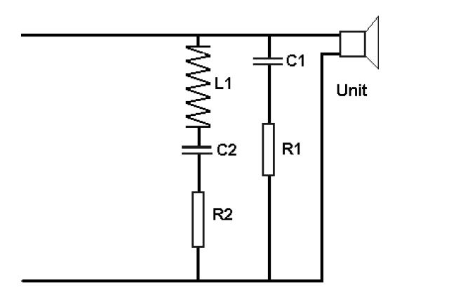
And you can play with parallelling series first filters as we often do:
Or shunt first filters in series:
Both around 8 ohms flat except for the bass Fs peak which is expensive to fix. They end up looking identical on response!
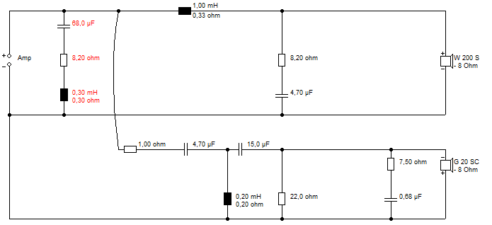
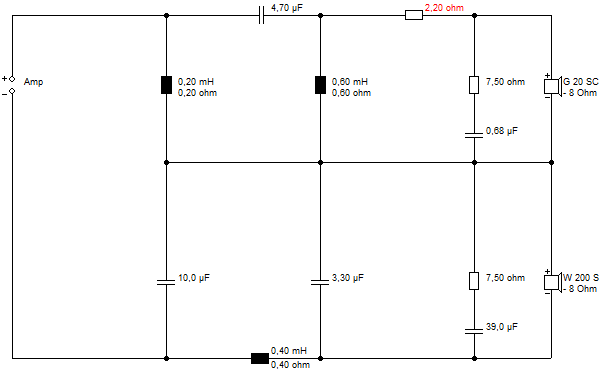
Flat Impedance and Flat Power response design.
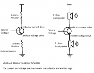
Thought experiment I did was to imagine a very idealised Class A amplifier. The top loudspeaker gets current drive, the bottom one voltage drive. They end up in the same place to me! 😀
Different solutions, but all can be made to work in different applications.
You might equalise the impedance of a loudspeaker:
And you can play with parallelling series first filters as we often do:
Or shunt first filters in series:
Both around 8 ohms flat except for the bass Fs peak which is expensive to fix. They end up looking identical on response!
Flat Impedance and Flat Power response design.
Thought experiment I did was to imagine a very idealised Class A amplifier. The top loudspeaker gets current drive, the bottom one voltage drive. They end up in the same place to me! 😀
Attachments
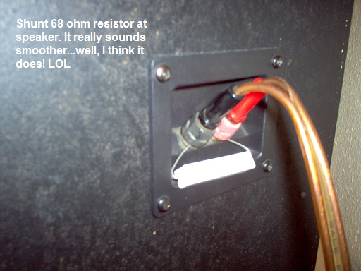
Well...I did it and The Sound is pretty marvelous. Nothing I'd "kick out of bed" anytime soon! It was pretty good before I did this, I might note. Unsure if I dare say it's better, but it's definitely no worse as far as I can tell. The foot taps...
Could someone please explain "how it works"? I used an 8 Ohm non-inductive in series with the 8 Ohm tap; which is supposedly 0.7 Ohms looking into it with my 8 Ohm Pluvias connected to the 90 Ohm secondary tap.
I'm 3 clicks down from WFO on the amp volume to get to a pleasant listening level. The directly connected 4 ohm driver H frames are ~15 db below the 8 ohm FR drive level, to get near balanced and maybe can go lower still. Lucky for me I dont enjoy listening loudly - I'd need a new amp. It's stretched to where I cant compensate for different modulation levels across media.
Attachments
I am not sure what you are doing there, but I have had a similar experience:
Maybe something to do with feedback amplifiers. Maybe stops high frequency near oscillations. I don't know.
Maybe something to do with feedback amplifiers. Maybe stops high frequency near oscillations. I don't know.
I'm getting this strange Petr_2009 feeling
Petr_2009 had at least the excuse of language.
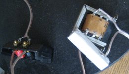
I did the "Clean-Current Full-Range Speaker CCS-7", but without all the EQ parts - just the transformer. I used a different transformer as well, with an 8 to 90 ohm primary to secondary. Idea courtesy of Esa Merilainan (sorry I dont know how to code the umlaut; alt+0228 doesnt work for me)
To KSTR: Please don't preach basics to me. It is rather condescending. And you were not a fly on the wall when I spoke to Richard Small.
Last edited:
- Home
- Member Areas
- The Lounge
- The Black Hole......