Had a couple of pro PA amplifiers here for awhile. Yes they had internal DSP, and networking connectors for remote programming. They were some old Crown units that came with some JBL M2 speakers here on loan. While probably not the best example of more modern pro PA amps, the class-D amps inside the boxes had analog inputs, so the SigmaStudio DSP chips drove some middle of the road AKM dacs to produce the needed analog line level signals. Internally the DSPs ran at 96kHz and used ASRC on incoming audio. There was also an ADC to handle analog inputs.
Those power amps sounded awful unless the volume level was turned up deafening levels, which seemed to have a masking effect.
The M2 speakers sounded much better without the DSP, just simple bi-amping with linear power amps and an analog line level crossover. Yes, they still needed more FR correction, but even without that they were at least listenable to me.
Last edited:
Those power amps sounded awful unless the volume level was turned up deafening levels, which seemed to have a masking effect.
Yet the owner (and we all know who he is) said it was the best he had ever heard, and good enough to hear the difference between a normal benchmark DAC and one that someone had filled with brown glorp. Funny old world...
The studio guys don't seem to complain either.
That means you measured it. Lets see some of it.Yes, they still needed more FR correction,
To you, which doesn't mean anything to readers on the other side of computer screen. 🙄but even without that they were at least listenable to me.
...good enough to hear the difference between a normal benchmark DAC and one that someone had filled with brown glorp...
Why assume a particular type of noise and or distortion must mask plainly obvious differences in other connected components? That rarely seems to be the case. Not even in the drastic case of very distorted guitar amps. One can still hear the effects of the various pedals.
Well unless the brown quatermass gloop added wrecked the performance of one same the two DACs should have sounded the same as Benchmark pride themselves on their QA as a supplier to professionals.
I believe the crown model mentioned uses a Cirrus DAC and ADC. Acceptable performance but nothing high end. So using that combination to try to hear the difference between two high end DACs seems a fools errand.
Using a DAC at all on a DSP amplifer with digital inputs doesn't make any sense to me mind.
IIRC, the digital input was 96kHz AES only. Amplifiers, including their data converters, were dual mono. Didn't have an AES source handy at the time. Anyway, there were audible dac differences between the two Benchmarks. Differences were easily audible although I would not say the differences were equally as audible as they might have been under more favorable circumstances.
Regarding my DAC-3, eventually I got a Topping D90. Compared those two dacs using my big electrostat panels. While not perfect, D90 easily bettered DAC-3 in terms of producing a good stereo illusion. Much wider and somewhat deeper soundstage. DAC-3 was compressed in between the middle of the speakers and forward. D90 was wide and reasonably deep. But the difference might only matter to a 'space junkie.'
Regarding my DAC-3, eventually I got a Topping D90. Compared those two dacs using my big electrostat panels. While not perfect, D90 easily bettered DAC-3 in terms of producing a good stereo illusion. Much wider and somewhat deeper soundstage. DAC-3 was compressed in between the middle of the speakers and forward. D90 was wide and reasonably deep. But the difference might only matter to a 'space junkie.'
Last edited:
I'm turning in circles with a mathematical problem, where I couldn't figure out a better place to go then right into the Black Hole where all intelligence is bundled together..
For a complex Z one can write Z = A +jB
Now when figuring out what capacitance Z has, I see two ways of calculating with two different outcomes, which can't be true but I don't see what I'm doing wrong.
Capacitor impedance is 1/(jwC) where w is 2(pi)f.
method 1)
1/(jwC) = A + jB or jwC = 1/(A+jB)
jwC = (A-jB)/[(A+jB)*(A-jB)] = (A-jB)/(A^2+B^2)=A/(A^2+B^2) -jB/(A^2+B^2)
So jwC = -jB/(A^2+B^2) giving C=-[B/(A^2+B^2)]/w
method 2)
1/(jwC) =A + jB or j/(j^2wC)= j/(-wC) = A+jB
then j/(-wC) = jB giving C = -1/wB
For very small values of A, result in both cases is -1/wB.
Method 2) with -1/wB is what I see being used by VNA's and is called "series capacitance".
But when measuring a DUT as a black box, nobody knows whether it has a series or a parallel cap inside.
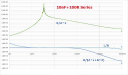
To illustrate some, I have added two images, one for 100R +10nF in series and one for 100R + 10nF in parallel.
Shown are both the 1/B and the B/(A^2+B^2) calculation, but also as additional info B/A^2 that would result for very small values for B, that happens not to be case here.
Obvious is that for the series connection 1/B gives a wider frequency band for C=10nF, but for a parallel connection it's almost unusable.
So who can tell me what I'm overlooking and why VNA's are using this 1/B method.
Hans
.
For a complex Z one can write Z = A +jB
Now when figuring out what capacitance Z has, I see two ways of calculating with two different outcomes, which can't be true but I don't see what I'm doing wrong.
Capacitor impedance is 1/(jwC) where w is 2(pi)f.
method 1)
1/(jwC) = A + jB or jwC = 1/(A+jB)
jwC = (A-jB)/[(A+jB)*(A-jB)] = (A-jB)/(A^2+B^2)=A/(A^2+B^2) -jB/(A^2+B^2)
So jwC = -jB/(A^2+B^2) giving C=-[B/(A^2+B^2)]/w
method 2)
1/(jwC) =A + jB or j/(j^2wC)= j/(-wC) = A+jB
then j/(-wC) = jB giving C = -1/wB
For very small values of A, result in both cases is -1/wB.
Method 2) with -1/wB is what I see being used by VNA's and is called "series capacitance".
But when measuring a DUT as a black box, nobody knows whether it has a series or a parallel cap inside.
To illustrate some, I have added two images, one for 100R +10nF in series and one for 100R + 10nF in parallel.
Shown are both the 1/B and the B/(A^2+B^2) calculation, but also as additional info B/A^2 that would result for very small values for B, that happens not to be case here.
Obvious is that for the series connection 1/B gives a wider frequency band for C=10nF, but for a parallel connection it's almost unusable.
So who can tell me what I'm overlooking and why VNA's are using this 1/B method.
Hans
.
Attachments

Last edited:
But when measuring a DUT as a black box, nobody knows whether it has a series or a parallel cap inside.
If it conducts DC current it has a parallel cap inside.
If it conducts DC current it has a parallel cap inside.
See pages 110-112 here.
https://assets.testequity.com/te1/Documents/pdf/impedance-measurement-handbook.pdf
https://assets.testequity.com/te1/Documents/pdf/impedance-measurement-handbook.pdf
Most likely reason is listening with the levels mismatched. That plus aural memory fade and listening position inconsistency.Compared those two dacs using my big electrostat panels. While not perfect, D90 easily bettered DAC-3 in terms of producing a good stereo illusion. Much wider and somewhat deeper soundstage. DAC-3 was compressed in between the middle of the speakers and forward. D90 was wide and reasonably deep.
...
method 1)
1/(jwC) = A + jB or jwC = 1/(A+jB)
jwC = (A-jB)/[(A+jB)*(A-jB)] = (A-jB)/(A^2+B^2)=A/(A^2+B^2) -jB/(A^2+B^2)
So jwC = -jB/(A^2+B^2) giving C=-[B/(A^2+B^2)]/w
In method 1 going from line 1 to line 2, you made the implicit assumption that A=0.
If it isn't, you need to include a series resistance term in the LHS equation so:
line 1: R + 1/(jwC) = ...
line 2: 1/[R + 1/(jwC)] = ...
Thank you Steve, your comment is most welcome.
However I don’t understand what R you are referring to.
C has an imaginary impedance 1/jwC, so I have to find out which part of 1/(A+jB) is that imaginary part that I’m looking for.
No assumption is made that A = 0
At the end I still have A in the equation together with B
Hans
However I don’t understand what R you are referring to.
C has an imaginary impedance 1/jwC, so I have to find out which part of 1/(A+jB) is that imaginary part that I’m looking for.
No assumption is made that A = 0
At the end I still have A in the equation together with B
Hans
If A is not zero, then you need to include a resistive term on the LHS before inverting both sides.
R + 1/(jwC) = A + jB
1/[R + 1/(jwC)] = 1/(A + jB)
(R-1/(jwC))/[(R-1/(jwC))*(R+1/(jwC))] = (A-jB)/[(A+jB)*(A-jB)]
(R–1/(jwC))/(R^2+1/(wC)^2) = (A-jB)/(A^2+B^2)
So
R/(R^2+1/(wC)^2) = A/(A^2+B^2)
And
(j/(wC))/(R^2+1/(wC)^2) = -jB/(A^2+B^2)
giving by inspection
1/(wC)= -B
resulting in
C = -1/(wB)
R + 1/(jwC) = A + jB
1/[R + 1/(jwC)] = 1/(A + jB)
(R-1/(jwC))/[(R-1/(jwC))*(R+1/(jwC))] = (A-jB)/[(A+jB)*(A-jB)]
(R–1/(jwC))/(R^2+1/(wC)^2) = (A-jB)/(A^2+B^2)
So
R/(R^2+1/(wC)^2) = A/(A^2+B^2)
And
(j/(wC))/(R^2+1/(wC)^2) = -jB/(A^2+B^2)
giving by inspection
1/(wC)= -B
resulting in
C = -1/(wB)
Well not suprising as the ADC/DAC and digital filtering all run at that rate.IIRC, the digital input was 96kHz AES only.
That would be a problem with the speaker's owners not you.Didn't have an AES source handy at the time.
Despite going through a cheap ADC/DAC? I'm having trouble with that.Anyway, there were audible dac differences between the two Benchmarks. Differences were easily audible
While not perfect, D90 easily bettered DAC-3 in terms of producing a good stereo illusion. Much wider and somewhat deeper soundstage. DAC-3 was compressed in between the middle of the speakers and forward. D90 was wide and reasonably deep. But the difference might only matter to a 'space junkie.'
Soundstage depth is usually a frequency anomaly in the 1-3kHz region. For a DAC to affect width significantly would worry me as there is no obviousl mechanism unless something is very wrong like an inverted channel or very poor crosstalk. I doubt differences in digital filters could do that, but happy to be proven wrong.
If A is not zero, then you need to include a resistive term on the LHS before inverting both sides.
So, this is a divide-by-zero singularity?
I'm imagining being 15 and being able to follow along, but it's much later and I can't keep up.
All good fortune,
Chris
If A is not zero, then you need to include a resistive term on the LHS before inverting both sides.
R + 1/(jwC) = A + jB
What you say in fact is my method 2:
A - j/(wC)= A +jB.
resulting in
C=-1/(wB)
What is still a bit of a mystery to me is why this is called a series capacitance.
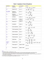
See image with definitions below.
Cs = -1/(wB) and Cp is corrected with the term 1+D^2 where D = A/B
Cp = Cs/(1+D^2) = -B/(A^2+^B^2)
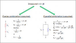
So my method 1 gave the Cp value and method 2 the Cs value 😀 😀
That's why the graph in #7347 was so much better for the Parallel version.
Hans
.
Attachments
Both method 1 and 2 should give you identical results since 1 just uses the inverse of 2 as the starting point. What I was trying to get at is that when taking the inverse of a complex number you have to include both real and imaginary terms unless you know in advance that the real term is zero. Taking inverse of real and inverse of imaginary parts separately is incorrect method of complex division.What you say in fact is my method 2:
Cs is called series capacitance because the value calculated will be constant over a broader range of frequencies if the circuit you are measuring is best represented by a series connection of a capacitor and a resistance. Similarly Cp is called parallel capacitance because the value calculated will be constant over a broader range of frequencies if the circuit you are measuring is best represented by a parallel connection of a capacitor and a resistance. Your plots from Post#7347 illustrate this.What is still a bit of a mystery to me is why this is called a series capacitance.
Suppose you were given a black box and told it contained a resistor and a capacitor. You then measured it and determined Z= A + jB for a range of frequencies. At every specified frequency, the impedance could be represented by either a series or parallel combination of a resistive and reactive(capacitive in your case) components. Whichever combination is actually in the black box will produce a constant calculated value for capacitance. So if calculated Cs values are more uniform than Cp across the frequency range, the components are in series. If calculated Cp is more uniform then they are in parallel.
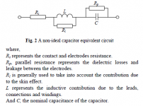
At the risk of telling you something you already know…real components can be a combination of series and parallel components. A commonly used equivalent circuit for a non-ideal capacitor is attached. If leads are kept short, it winds up being just C with Rp and Rs. In general Rp>>Rs so Cs is generally the appropriate calculation when measuring just a capacitor. More details in links below, or likely also in your VNA manual.
See section on Capacitance measurement.
http://www.componentsengineering.com/wp-content/uploads/pdfs/LCR-Measurement-Primer.pdf
Capacitors – Losses (ESR, IMP, DF, Q) – Passive Components Blog
Attachments
Hi Steve,
Yes I agree that method 1 should have included the real value A and for that reason gave a different outcome as method 2, that was exactly the reason for me to start my posting because this could not be the case.
But by accident the outcome of method 1 just gave me Cp.
Your explanation for the difference between Cs and Cp is the best I have seen,
so again thanks a lot for your contribution.
Hans
Both method 1 and 2 should give you identical results...
Steve,
Great explanation, and I wanted to thank you as well for your fantastic work on segmented ES panels....great stuff that renewed my interest in ES speakers. I have always wanted to build a pair since listening to Beverages back in the later 1970s and segmented ES really looks elegant.
Cheers!
Howie
As we had some discussions on here a while back on current drive and I think Pavel did some tests that did show current drive reducing distortion in the midrange considerably (although his website only has the tweeter results) I thought this might be of some interest and was linked over in the multi-way forum a couple of days ago.
Some Speaker Problems That Needed Solving | audioXpress
Interestingly the Purifi team are quoting a 15dB distortion reduction with current drive as well as giving a possible mechanism and a fix for it in their drive units.
I'm sure this current drive midrange has been used in some studio active monitors and wouldn't suprise me if the Kii3 does similar but I guess the general dislike of active speakers by the audio buying public stops this being more widely implemented/discussed?
- Home
- Member Areas
- The Lounge
- The Black Hole......